

In-vivo real-time photo-sensitive blood pH value sensor and its making method
A ph sensor, time technology, applied in the field of medical equipment and materials, to achieve the effect of rapid response, stable performance and long service life
- Summary
- Abstract
- Description
- Claims
- Application Information
AI Technical Summary
Problems solved by technology
Method used
Image

Examples
Embodiment 1
[0021] Dissolve 30 grams of MPC, 68 grams of butyl methacrylate, 2 grams of γ-(methacryloyloxy)propyltrimethoxysilane and 0.1 gram of initiator AIBN in absolute ethanol, and slowly introduce argon for 1 hour deoxygenation. Then place it in a constant temperature water bath at 70° C., and react under stirring for 24 hours. After the reaction was completed, the solution was cooled to room temperature and purified twice by precipitation with a large amount of n-hexane; the collected precipitate was vacuum-dried at room temperature for 24 hours. 90 grams of copolymers containing phospholipid groups were obtained.
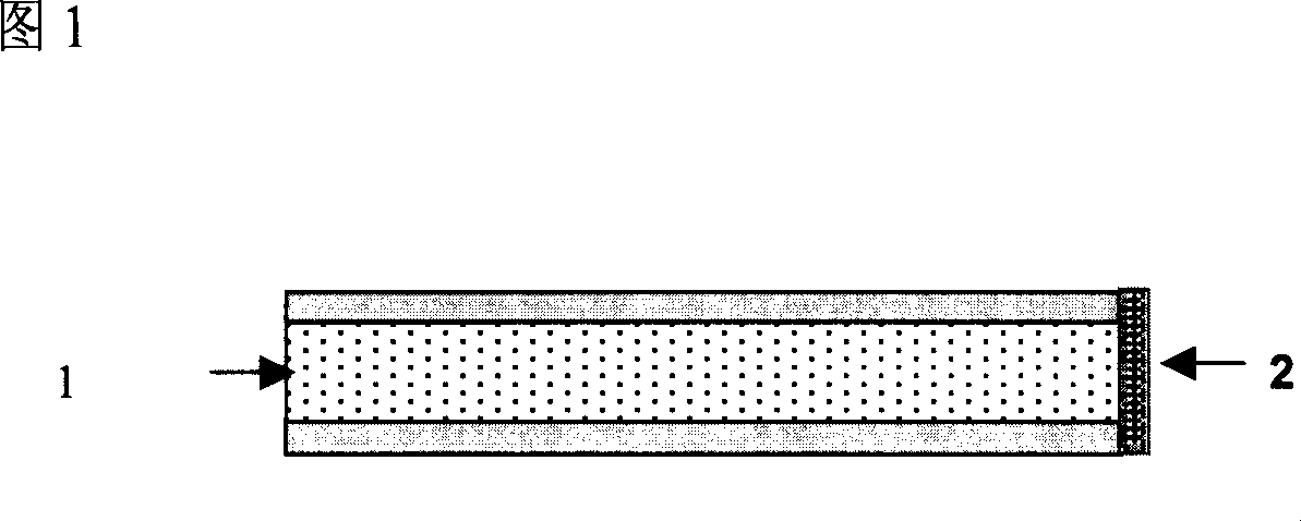
[0022] Dissolve 50 mg of BCECF in 10 ml of methanol, and dissolve 0.4 g of the above-mentioned copolymer containing phospholipid groups in the same solution. After filtering, add 20 microliters of water to the resulting solution, stir evenly, and apply the solution on the optical fiber. The end is heat-treated in a 70-degree oven for 5 hours to volatilize the solvent ...
Embodiment 2
[0024] 15 grams of MPC, 10 grams of polyethylene glycol (molecular weight 360) methyl ether methacrylate, 10 grams of ethylene glycol methyl ether methacrylate, 63 grams of dodecyl methacrylate, 2 grams of γ-( Dissolve methacryloyloxy)propyltrimethoxysilane and 0.1 g of initiator AIBN in anhydrous ethanol / tetrahydrofuran (volume ratio 50 / 50) solution, and slowly pass through argon gas for 1 hour to remove oxygen. Then place it in a constant temperature water bath at 70° C., and react under stirring for 24 hours. After the reaction was completed, the solution was cooled to room temperature and purified twice by precipitation with a large amount of n-hexane; the collected precipitate was vacuum-dried at room temperature for 24 hours. 92 grams of copolymers containing phospholipid groups were obtained.
[0025] Dissolve 30 mg of BCECF in 5 ml of methanol, and dissolve 0.2 g of the above-mentioned copolymer containing phospholipid groups in the same solution. After filtering, add...
PUM
 Abstract
Description
Claims
Application Information