Method and apparatus for optical recording of biological parameters in freely moving animals

a biological parameter and optical recording technology, applied in the field of measuring biological processes in freely moving animals, can solve the problems of general cell biological interpretations of both normal and abnormal, general cell biological interpretations of non-laminar brain structures, and general uninformative analyses in non-laminar brain structures, etc., to reduce low frequency noise and reduce cross talk

Inactive Publication Date: 2019-05-21
THE BOARD OF TRUSTEES OF THE LELAND STANFORD JUNIOR UNIV
View PDF27 Cites 17 Cited by
  • Summary
  • Abstract
  • Description
  • Claims
  • Application Information

AI Technical Summary

Benefits of technology

[0011]In the illustrative embodiment, the optical measurement / recording system includes two single-mode, fiber-coupled lasers, one of which at 488 nm and the other at 561 nm. The lasers are amplitude-modulated by a function generator and optically coupled into a fiber-optic cable. In accordance with the illustrative embodiment, to reduce low frequency noise, the laser sources are amplitude modulated at 900 Hz and all optical signals are read-out via lock-in amplifiers. To reduce cross talk, the 561 nm laser source is phase-shifted (e.g., 90 degrees, etc.).
[0019]iii. The use of phase-multiplexed amplitude-modulation of excitation sources to remove flicker noise and practical minimize cross-talk between excitation sources (when multiple sources are present).
[0020]iv. The use of single-mode excitation sources to prevent auto-fluorescence due to the excitation of fiber cladding modes. Multimode optical fiber offers high numerical aperture (“NA”), but auto-fluorescence generation and bending-induced artifacts during animal behavior can be problematic. In the illustrative embodiment, a flexible 0.39 NA fiber with 400 micron core diameter was used in conjunction with 5-axis alignment of single-mode excitation lasers to reduce auto-fluorescence generated in the polymer cladding to an order of magnitude below signal levels.

Problems solved by technology

This mechanistic complexity has precluded general cell biological interpretations of both normal and pathological electric field oscillations, especially in deep-brain regions.
These analyses are, however, generally uninformative in non-laminar brain structures such as the striatum that contain intermingled, heterogeneous cell types.
Electrophysiological approaches for measuring intracellular voltage dynamics are usually limited to recordings in single cells and are also nearly prohibitive to perform in a manner that targets specific cell types in behaving animals, especially in sub-cortical brain areas.
However, intracellular [Ca2+] is an indirect correlate of membrane depolarization, is a poor proxy of spiking activity in many cell types, tracks neither subthreshold, inhibitory, nor oscillatory neural activity well, and does not report fast dynamics on timescales finer than about 25 to 50 milliseconds.
These limitations preclude the use of Ca2+ indicators as a general means of tracking large-scale brain oscillatory dynamics in live mammals.
An even more persistent obstacle to the use of both genetically-encoded and synthetic fluorescent voltage sensors is recording noise introduced by photon-shot noise.
No prior optical system has had the detection sensitivity needed to overcome the shot noise and physiological artifacts that are unavoidably present in optical recordings in unrestrained animals and to monitor voltage oscillations in freely behaving mammals.

Method used


Image

  • Method and apparatus for optical recording of biological parameters in freely moving animals
  • Method and apparatus for optical recording of biological parameters in freely moving animals
  • Method and apparatus for optical recording of biological parameters in freely moving animals

Examples


first embodiment

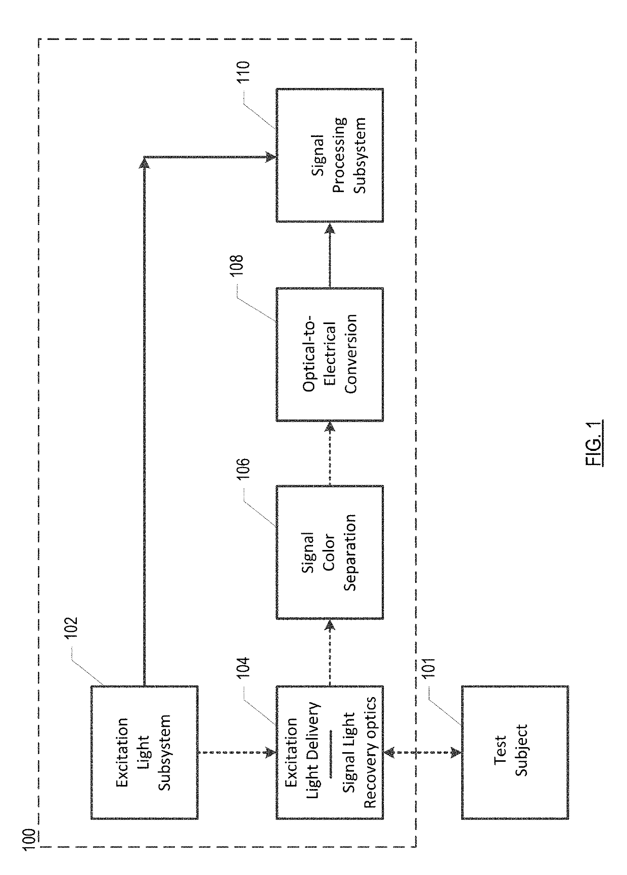
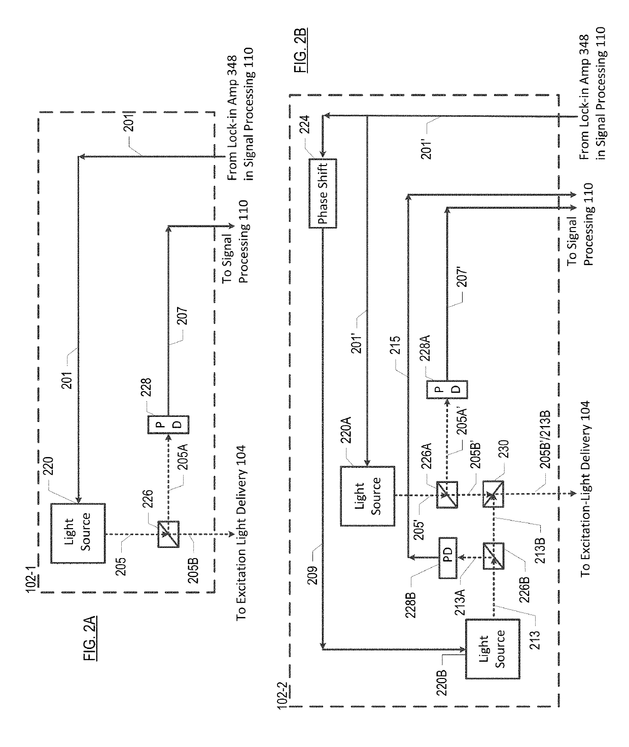
[0066]FIG. 2A depicts an excitation-light subsystem in accordance with the present teachings. Subsystem 102-1 includes a single excitation-light source 220, beam splitter 226, and photodetector 228 in a free-space-optics arrangement and interrelated as shown.

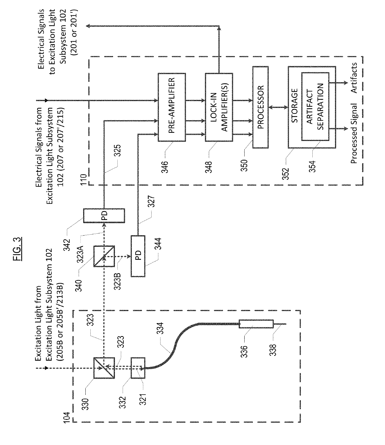
[0067]Light source 220 generates light 205. In this embodiment, light source 220 is a laser, although other sources of light may suitably be used in combination with a filter, etc., as appropriate, to provide a narrow-band source. Light source 220 is modulated by signal 201, which is generated by one of lock-in amplifiers 348 in signal processing subsystem 110. Pre-processing light 205 in this fashion reduces low-frequency noise in the measurement of fluorescence at photodetectors 342 and 344 (see FIG. 3).

[0068]Light 205 is directed to beam splitter 226, wherein, in the illustrative embodiment, it is divided 50 / 50 in intensity. Portion 205A of light 205 is directed to photodetector 228, which generates corresponding electrical-d...

second embodiment

[0069]FIG. 2B depicts an excitation-light subsystem in accordance with the present teachings. Subsystem 102-2 includes light sources 220A and 220B, phase shifter 224, beam splitters 226A, 226B, 230, and photodetectors 228A and 228B.

[0070]Light source 220A generates light 205′. In this embodiment, light source 220A is a laser, although other sources of light may suitably be used in combination with a filter, etc., as appropriate, to provide a narrow-band source. In the illustrative embodiment, Light 205′ is modulated at a single frequency by signal 201′, which is generated by one of lock-in amplifiers 348 in signal processing subsystem 110.

[0071]Light source 220B generates light 213 having a different wavelength than light 205′. Light 213 is modulated at a single frequency by signal 201′. Light 213 is also phase shifted by 90 degrees relative to light 205′ by phase shifter 224. The phase shift between 205′ and 213 will help prevent cross talk between the fluorescence that is ultimate...


PUM


Abstract

A system and method for monitoring biological parameters in freely moving animals that, in the illustrative embodiment, comprises a two-color optical measurement / recording system that is combined with a fluorescent protein reporter of cellular membrane potentials and a fluorescent protein that is insensitive to such cellular membrane potentials. The two wavelengths are used to un-mix physiological artifacts in recordings that occur in freely moving animals.

Description

STATEMENT OF RELATED CASES[0001]This case claims priority to U.S. Pat. Application 62 / 079,118, filed Nov. 13, 2014 and which is incorporated by reference herein. U.S. Pat Application 62 / 253,294, filed Nov. 10, 2015, is incorporated by reference herein.FIELD OF THE INVENTION[0002]The present invention relates to the measurement of biological processes in freely moving animals.BACKGROUND OF THE INVENTION[0003]Measurements of extracellular electric field potentials are widely used in clinical diagnostics and across a broad range of research contexts in cognitive psychology, neurophysiology, and systems neuroscience. Different forms of electroencephalographic (EEG) oscillations and event-related potentials are indicative of various brain states that are associated with distinct behaviors, modes of cognition and disease. In most cases, however, the physiological origins, functional importance and computational roles of electrical potential dynamics and their intracellular correlates rema...

Claims


Application Information

Patent Timeline
Patent Type & Authority Patents(United States)
IPC IPC(8): A61B5/00
CPCA61B5/0071A61B2503/40A61B5/4064
Inventor MARSHALL, JESSE D.SCHNITZER, MARK J.
Owner THE BOARD OF TRUSTEES OF THE LELAND STANFORD JUNIOR UNIV
Why Eureka
Try Eureka