Method of manufacturing an energy efficient electrical conductor

a manufacturing method and technology for electrical conductors, applied in the field of electrical conductors, can solve the problems of limiting the current carrying capacity of the conductor, requiring special devices and extra labor time from the linemen, and the cost of gap conductors is typically high, so as to reduce thermal sag, reduce thermal sag, and eliminate tensile stress

Active Publication Date: 2019-05-28
TS CONDUCTOR CORP
View PDF4 Cites 0 Cited by
  • Summary
  • Abstract
  • Description
  • Claims
  • Application Information

AI Technical Summary

Benefits of technology

[0021]The encapsulating conductive material may reach up to 500° C. or higher temperatures during conforming, quenching of the conductive material (e.g., aluminum, aluminum alloy, copper or copper alloy, etc.) effectively limits exposure time of strength member (such as high temp steel, composites of polymeric matrix) to such high temperatures to preserve the integrity and property of the strength members (s). The adhesion and compaction of conductive material around the strength member(s) at ambient or sub ambient temperatures are important to preserve the effect of residual tensile stress in the strength member(s), otherwise, the higher CTE conductive material will exert a compressive stress onto the strength member of lower thermal expansion coefficient, diminishing the effect of pre-tensioning onto the strength members.
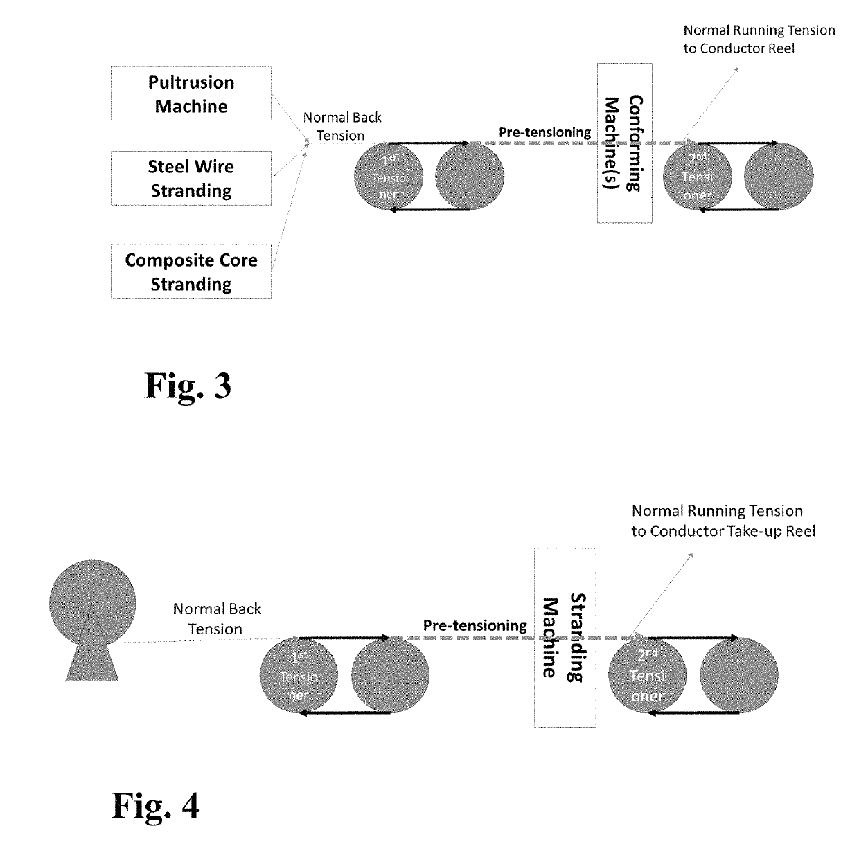
[0025]It is recognized in the patent that additional pre-stress conditioning of the above mentioned conductors can be accomplished by subjecting the conformed conductors to the following paired tensioner approach or trimming the pre-determined encapsulated core length before deadending, all accomplished without exerting the high tensile stress to the tower arms required to pre-tension conventional conductors in the electric towers. For example, the conductors mentioned above are subjected to pre-tensioning treatment using sets of bull wheels prior to the first sheave wheel during stringing operation, without exerting additional load to the electric towers. This can be simply done by two sets of tensioners, with the first set maintaining normal back tension to the conductor drum / reel, while the second set restoring the normal stringing tension to avoid excessive load to electric towers, especially those old towers in reconductoring projects. The conductor is subjected to the pre-tensioning stress between the 1st and 2nd tensioners, typically about 2× of the average conductor every day tensile load to ensure that the pre-tensioning is driving its knee point below the normal operating temperature so that aluminum strands are not in tension for optimal self-damping and the conductor is virtually not changing its sag with temperature. It should be noted that larger bull wheels in the tensioners and larger sheave wheels will help in managing the minor loosening in the outer layer aluminum strands. While it is possible to apply the methodology described here for factory based conductor pre-tensioning during stranding (optional final step), which might be what was practiced in the Chinese patent (undisclosed), it is possible, and maybe manageable, but not advisable for conductors of multi-layer stranding because such conductors in the reel may suffer significant and serious deformation and damage to aluminum strands, especially the inner layer of strands, on the conductor reel, after pre-tensioning treatment in the stranding line, resulting in significant birdcaging and conductor handling issues (core restraining devices must also be applied to avoid the core from retracting inside the conductor). The process described here is equally applicable to conventional ACSS, ACSR, ACCC, ACCR, Lo-Sag, C7, Invar conductor or like conductor types that are made of differing materials between the conductive constituent and strength member(s) to effectively shift conductor thermal knee point without exerting high pre-tension stress to electric towers.
[0027]While the conductors described in the invention are mostly for high temperature applications, these conductors can also be considered for green field new transmission projects where reduced thermal knee point reduces thermal sag, increases line capacity. Pre-tensioning also eliminates tensile stress in the conductive material (aluminum or copper and their respective alloys), resulting in exceptional self-damping and the possibility of higher erection tension that reduces conductor tendency for galloping as well as fewer and shorter towers to lower the project construction costs. Shorter towers are also environmentally more appealing to the utility and the community it serves. The encapsulation layer also functions in a similar function as the extra aluminum sleeve required in the AFL fitting for conductors with composite strength members, making it compatible with all conventional compression fittings without any additional pieces, tools or special training. In some characterization, the length of the steel tube in conventional hardware may be lengthened to accommodate the higher strength encapsulated composite strength members, for example the clamping zone is increased in length of at least about 1%, such as at least 2%, and even at least 5%.
[0029]The present invention further enables robust handling of the conductors with composite strength members encapsulated and protected, where the effective diameter of the strength members is substantially increased to that of the encapsulation layer outer diameter, minimizing the possibility of extreme sharp angle to the inner strength member, and avoiding the occurrence of excessive axial compressive stress to the strength members inside the encapsulation. The pre-tension substantially preserved in the strength member, especially when it is made with fiber reinforced unidirectional composite, uniquely offsets the compressive stress arising from conductor bending or sharp angles, minimizing or even eliminating the dangerous risk of fiber compressive buckling failure in such composite core conductors. The encapsulated strength members can be directly fitted with conventional fittings where crimping and conventional low cost tools may be applied. With the surface being round and hermetically sealed, there is significant improved corrosion resistance as the pollutants cannot easily lodge into the conductor strands, and the composite strength members in these conductors are effectively shielded and protected from oxygen or moisture ingression, UV or Ozone degradation (unlike the existing conductor configurations). Unlike the coating applied to steel strength members in some commercial conductors (aluminum clad steel or invar) where the conductive cladding significantly increases the thermal expansion coefficient of the strength member and worsening sag performance, the encapsulating layer is of such sufficient thickness that it provides life time protection for the encapsulated member, including the galvanic corrosion protection, which has been experienced in commercial conductors when thin aluminum cladding layer was eroded from vibration in the conductor (e.g., aluminum strands against the thin aluminum cladding), and the galvanic pair of aluminum and steel in the presence of electrolyte (e.g., water or conductive pollutants) accelerates the corrosion inside the conductor, shortening conductor life. In one characterization, the conductor strength members, when also sealed at cut ends such as deadending or conductor splicing, there is no risk for moisture or conductive salt ingressing into the strength member, galvanic corrosion between carbon fiber composite and aluminum or copper encapsulating layer may not be an issue because of absence of electrolyte at the interface between strength member and encapsulating metal layer (which is required for corrosion to take place), and the strength members such as steel or carbon fiber composite may not require galvanic corrosion protective layers. In carbon fiber composite strength member, there may not be a need for insulation layer such as glass fiber composites or insulating polymeric layer. In another characterization, the strength member made of mostly, if not all, with glass or glass types of reinforcement fibers vulnerable to stress corrosion under tension load, can be deployed for long term conductor installation because of absence of moisture ingress into the strength member. The encapsulating or cladding material is under no tension or is under compression, and it does not impact the effective thermal expansion coefficient of the encapsulated strength member(s), preserving the low sag characteristics of the strength members from its lower thermal expansion coefficient.

Problems solved by technology

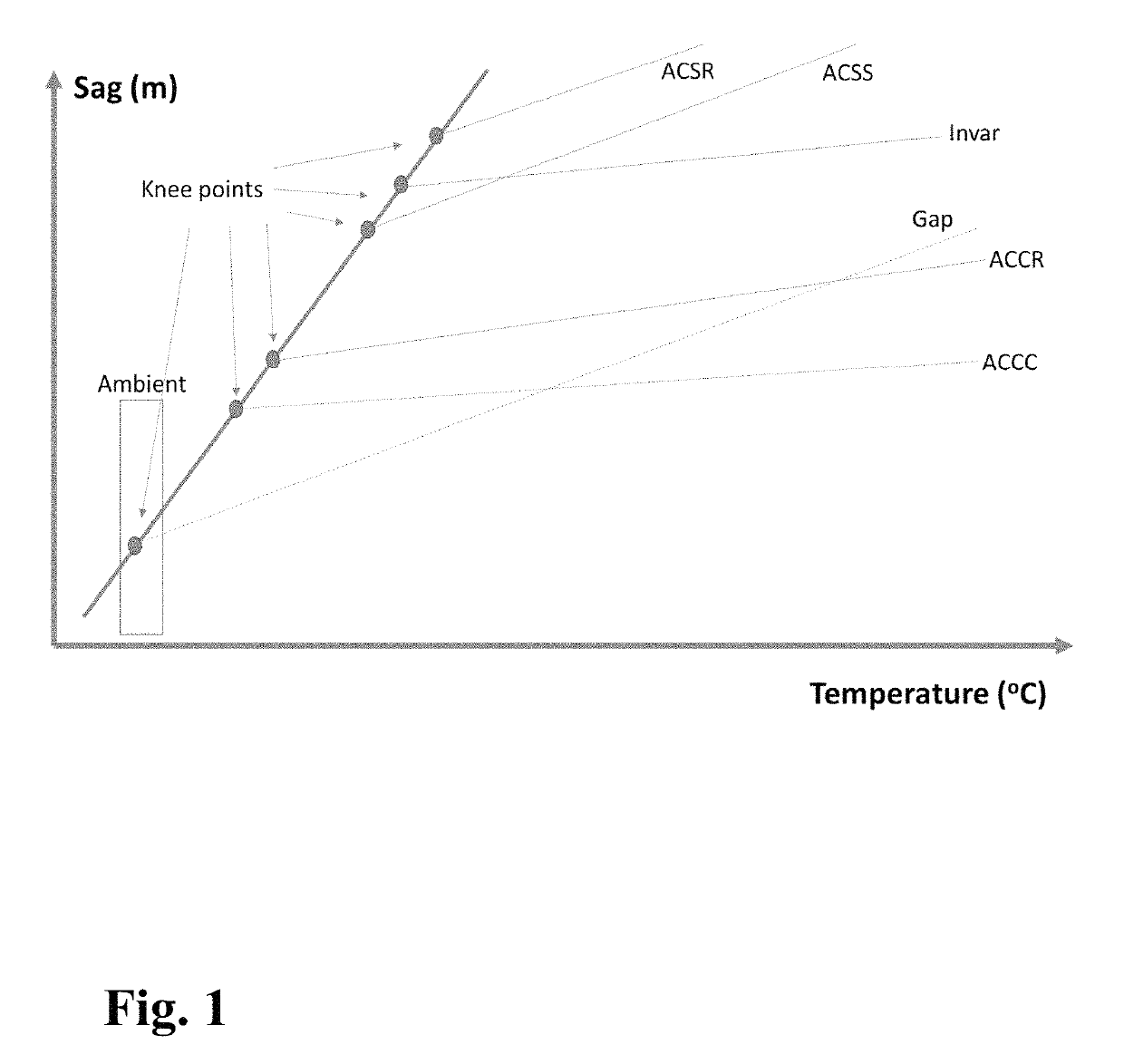
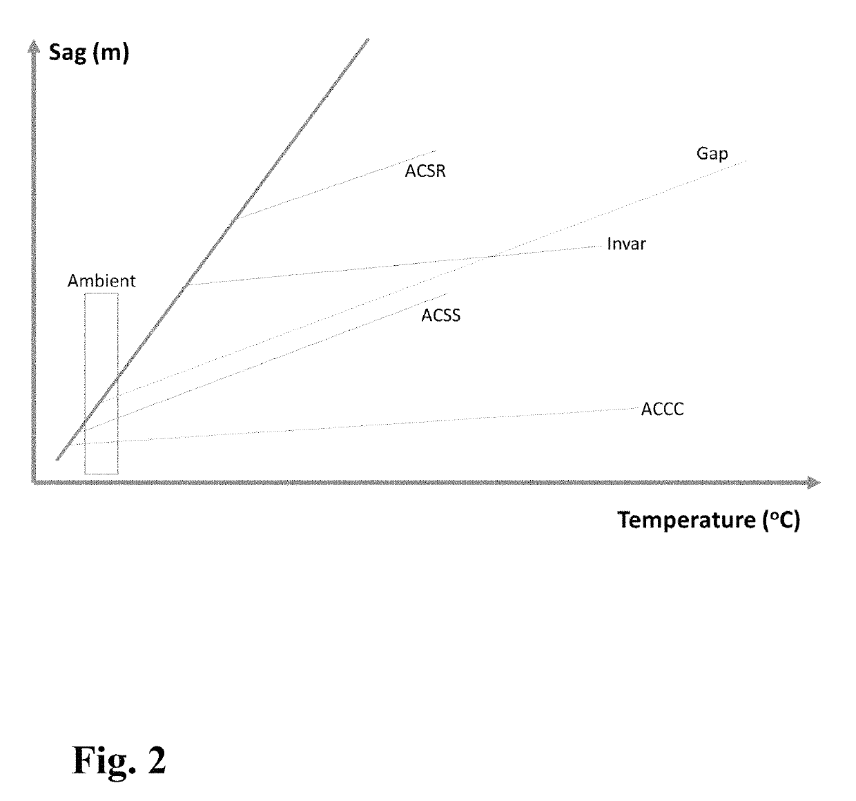
Until the conductor reaches above its thermal knee point, the conductor thermal expansion is substantially controlled by conductive material such as aluminum or copper with high thermal expansion coefficient, resulting in large sag, limiting the conductor's current carrying capacity, as shown in FIG. 1.
This tensioning process can be as long as 48 hours or more, and requires special device and extra labor time from linemen as the linemen have to revisit the towers for final deadending after the tensioning process.
However, Gap conductors are typically very expensive.
It is difficult to install, requiring special training and tools and significantly more labor time in the field.
Furthermore, since the conductor strength member is taking virtually all the load and it retracts inside the Gap conductor's aluminum layers if the conductor breaks, it is impossible to repair gap conductor in the field.
The entire conductor segment from deadend to deadend must be replaced and installed, resulting in costly delays in restoring electrical transmission.
The grease inside the gap conductor has being reported to leak out through the aluminum strands over time, staining objects under the power lines as well as corona noise due to water beading on conductor surface as a result of the hydrophobic greasy surface.
The grease in Gap conductor is also for protecting the steel wires from corrosion, and removal of the grease will result in compromised corrosion resistance of gap conductors.
When the conductor is wrapped in the take-up reel as typically done during conductor stranding manufacturing, the overlaying of these pre-stressed multi-strand conductors likely caused irreversible deformation of the annealed substantially loose / open aluminum strands in all the under layers of conductors.
These permanent deformation of aluminum strands will cause not only conductor birdcaging, but also localized deformed aluminum strands to break and causing hot spots and conductor failure during energized conductor operation.
The severely loose aluminum alloys strands posed same challenges.
The core in the conductor might be protected with a thin aluminum cladding in JPS approach for high temperature operation, however, the aluminum cladding on the core is also subjected to extreme tension as high as 190 MPa during the pre-stretching process of the core while aluminum strands are stranded, making it vulnerable to vibration fatigue.
The thin cladding is unable to sustain the tensioned core and minimize its shrinking inside the conductor that the ends of the conductor must be fixed before the tension in the core is released, forcing all the aluminum strands to be very loose.
The loose aluminum strands and the need to fix the conductor ends make it difficult to handle the conductors in both manufacturing and field stringing.
Pre-tensioning of ACSS does reduce thermal knee point and improve thermal sag, however, the high stress required in ACSS in tensioning increases risk to the safe operation of the transmission towers, especially for older transmission towers in reconductoring application projects.
It is uncommon for these conductors to be pre-stressed on existing towers as the older towers may not be capable of high level pre-tension required to substantially suppress conductor thermal knee point.
These composite core(s) are vulnerable to fiber buckling failure from excessive axial compressive stress during installation, such as the case in sharp angle situations associated with mishandling.
Conductors with smaller cores, with better bend flexibility, are ironically more vulnerable as these conductors do not require much bend stress to fail when subjected to sharp angle (with the aluminum strands in the stranded conductors, sliding to accommodate bending of the strength member), especially when tension on the composite strength member is absent.
Hardware costs for projects using such conductors sometimes are as high as 50% of total project cost, which is unacceptable, especially for cost sensitive applications such as lower voltage electrical distribution network.
Furthermore, these conductors must follow precisely prescribed stringing temperature and time duration, especially in bundled configurations during stringing, making the installation process prohibitively expensive.
If the tension and time history of the phase conductors are different, there could be different thermal knee points for each conductor and differential sagging among the bundled phase conductors after installation, causing flashing or even short circuits with changing conductor temperatures.
Such changes in conductor sag are not only substantial but also seemed random and unpredictable, a significant issue for field engineers and the electric utility.
Another challenge for conductors with carbon fiber polymeric composite core and annealed aluminum is their high sag in heavy ice environments.
This requires extra time and expensive effort from linemen.
This procedure will be unnecessary if a pre-tension treated conductor is used.
In electric distribution network, where it operates at lower voltage, conductors are subjected to higher current density due to cost constraints.

Method used


Image

  • Method of manufacturing an energy efficient electrical conductor
  • Method of manufacturing an energy efficient electrical conductor
  • Method of manufacturing an energy efficient electrical conductor

Examples


example 1

on for Reconductoring Applications in Transmission and Distribution Grid

[0069]Transmission line reconductoring is typically in voltage ranging from 110 kv to 500 kv, where existing towers are leveraged as much as possible to reduce project cost and power outage time. Reconductoring may also be done live line, where no outage is scheduled during reconductoring. The primary focus of reconductoring is to maximize line capacity within established clearance constraint and to leverage existing infrastructure. The conductor from this invention is ideal for such application, where the highest packing density in the conductor (almost 100% for the concentric layers, vs typically 93% fill factor in a tightly stranded conductor such as ACCC conductor from CTC Global) will provide the new conductors with highest possible capacity (and lowest resistance and lowest line loss) at normal operating conditions. For emergency conditions, where the conductor is exposed to high temperatures, the conducto...

example 2

on for New Build Applications in Transmission and Distribution Grid

[0075]New build projects often are more sensitive to materials and labor cost (e.g., conductor cost, fitting cost as well as tower cost). Some of the new builds are for long distance transmission and ultra-high voltage where corona effect must be controlled and conductor resistance and line loss must be minimized.

[0076]The embodiment in the invention include the option of stranding around the encapsulated pre-tensioned strength member(s) with additional layer(s) of conductive strands to increase conductor diameter for UHV applications while facilitating easy handling (requiring smaller reels for wrapping). For aluminum conductors in AC circuit of 60 Hz, the skin effect requires a maximum conducting layer thickness to be 17 mm. Large conductors must consider multi-layer configuration. Since significant amount of aluminum have already been pre-stressed under compression, the load and the time required to put the additi...

example 3

on for Special Situations: River Crossing and Ultra-Long Span, Heavy Ice and Corrosion Heavy Regions

[0079]River crossing or ultra-long span applications or heavy ice regions have the same need of compact conductors with high strength and modulus. If the transmission project is thermal sag constrained, partial or full thermal knee point suppression is desirable. If the transmission line sag clearance is driven by the ice load or weight of the conductor, it is desirable to use high strength light weight fiber reinforced composite strength member (s), and 1) either to leverage some or most of the aluminum alloy (such as Aluminum Zirconium alloys, 6201-T81) or copper and copper alloys in load carrying to minimize sag (with less suppression in conductor thermal knee point, i.e., the additional layers of conducting material (beyond the pre-tensioned encapsulating layer with the strength member) is not subjected to additional pre-tension treatment) or 2) to pre-tension the conductor suffic...


PUM

PropertyMeasurementUnit
thickaaaaaaaaaa
temperatureaaaaaaaaaa
Tgaaaaaaaaaa

Abstract

The present invention relates to electrical conductors for electrical transmission and distribution with pre-stress conditioning of the strength member so that the conductive materials of aluminum, aluminum alloys, copper, copper alloys, or copper micro-alloys are mostly tension free or under compressive stress in the conductor, while the strength member is under tensile stress prior to conductor stringing, resulting in a lower thermal knee point in the conductor.

Description

[0001]The present application is a divisional of U.S. Provisional application Ser. No. 14 / 863,396 filed on Sep. 23, 2015, now U.S. Pat. No. 9,633,766, which claims priority from U.S. Provisional Application Ser. No. 62 / 056,330 filed on Sep. 26, 2014 and from U.S. Provisional Application Ser. No. 62 / 148,915 filed on Apr. 17, 2014, which are each hereby incorporated herein by reference in their respective entirety.TECHNICAL FIELD OF THE INVENTION[0002]The present invention relates to electrical conductors for electrical transmission and distribution with pre-stress conditioning. In particular, the present invention relates to electrical conductors with strength members such as fiber reinforced composites. More specifically, the present invention relies upon pre-stress conditioning of the strength member so that the conductive materials of aluminum, aluminum alloys, copper, copper alloys, or copper micro-alloys are mostly tension free or under compressive stress in the conductor, while...

Claims


Application Information

Patent Timeline
Patent Type & Authority Patents(United States)
IPC IPC(8): H01R43/00H01B5/10H01B1/02H01B13/00H01R4/18H01B13/02
CPCH01B5/102H01B1/023H01B1/026H01B13/0016H01R4/183H01B5/105Y10T29/49123H01B13/0285
Inventor HUANG, JIANPING
Owner TS CONDUCTOR CORP
Why Eureka
Try Eureka