System and method for interleaved digital-to-analog converter (DAC) calibration

a digital-to-analog converter and calibration system technology, applied in transmission systems, physical parameter compensation/prevention, instruments, etc., can solve the problems of difficult to address timing errors, interleaved dacs are particularly susceptible to dynamic errors, interleaved dacs are more sensitive to timing errors, etc., to improve spectral performance (sfdr), improve sensitivity, and improve the effect of spectral purity in ultra-high speed operation

Active Publication Date: 2019-10-29
IQ ANALOG
View PDF4 Cites 10 Cited by
  • Summary
  • Abstract
  • Description
  • Claims
  • Application Information

AI Technical Summary

Benefits of technology

[0011]Disclosed herein is a calibration scheme that provides an effective method to detect and calibrate for duty cycle mismatch and time skew between different clock phases driving multi-gigabit per second (Gbps) interleaved digital-to-analog converters (DACs), improving its spectral performance (SFDR) using a low frequency loop. A multi-step calibration method employs a low speed analog-to digital converter (ADC) in a feedback loop to provide the error information. This calibration method is capable of providing high sensitivity (femtosecond-range) to both duty cycle and phase errors, enabling superior spectral purity in ultra-high speed operation.

Problems solved by technology

Performance degradation in this type of DAC is mainly derived from two mechanisms: 1) static errors related to current-source mismatch and finite output resistance; and, 2) dynamic errors, typically due to code dependencies (e.g. output impedance) and timing errors (e.g. duty-cycle and clock time skew), among others, which can be induced by layout asymmetry, process variation, mismatch, and parasitic effects.
Interleaved DACs are particularly susceptible to dynamic errors, especially if Return-to-Zero (RZ) modulation is utilized.
Although RZ signaling improves code-dependency and linearity by returning the switch control signals to a common (zero) state every sample period, the frequent transitions made synchronous to a high speed clock cause RZ-based interleaved DACs to be more sensitive to timing errors, including jitter, time skew, and duty-cycle mismatch between different clock phases.
While static errors can be somewhat easily fixed using foreground calibration loops, Dynamic Element Matching, and pre-distortion, timing errors are difficult to address, especially at ultra-high clock rates.
At ultra-high speed operation, the slightest deviation from these ideal values (FIG. 1C) is known to produce large spurious harmonic content, significantly impacting the output signal's SFDR (FIG. 1D).
However, the method described in the above-cited patent does not seem to be scalable (higher than interleave-by-2), and it does not provide for duty cycle calibration.
A comprehensive calibration device or method compatible with multi-Gbps operation is needed, and its lack leads to inevitable linearity and spectral performance degradation, which is mostly alleviated nowadays (but not fully addressed) through careful design and area consuming layout techniques.

Method used


Image

  • System and method for interleaved digital-to-analog converter (DAC) calibration
  • System and method for interleaved digital-to-analog converter (DAC) calibration
  • System and method for interleaved digital-to-analog converter (DAC) calibration

Examples


Embodiment Construction

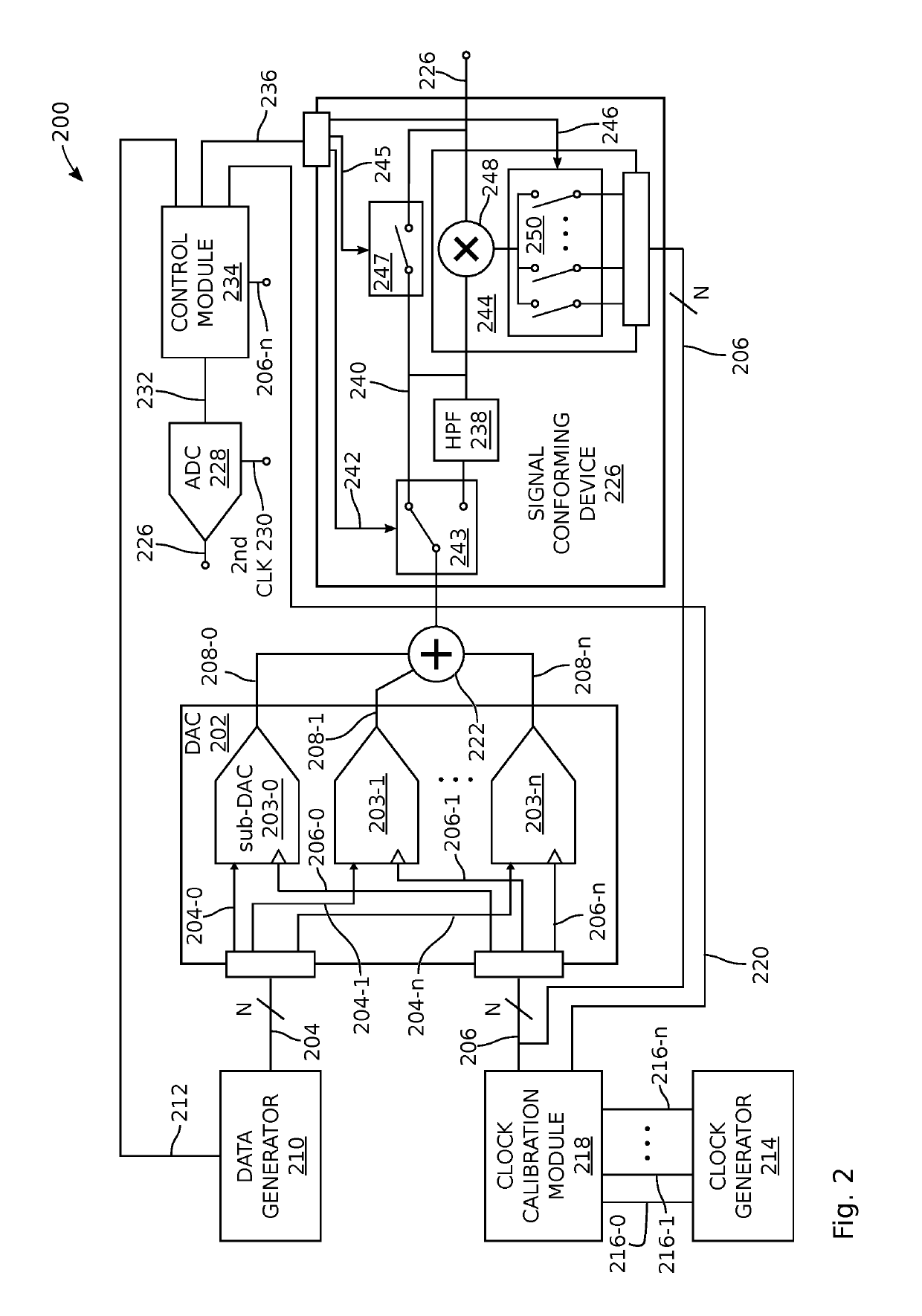
[0031]FIG. 2 is a schematic block diagram depicting a system for calibrating an interleaved digital-to-analog converter (DAC). The system 200 comprises an interleaved DAC 202, which, in turn, comprises 2N selectively enabled sub-DACs, 203-0 through 203-n, where N is an integer greater than or equal to 1. For example, the sub-DACs may be current-steering. However, the system is not limited to any particular type of DAC architecture. Each sub-DAC has an input, respectively on lines 204-0 through 204-n (bundled as 204), to accept a digital data signal, a clock input, respectively on lines 206-0 through 206-n (bundled as 206), to accept a first clock signal with unique phase, and an output, respectively on lines 208-0 through 208-n, to supply analog signals converted from the data signal.

[0032]A data generator 210 has 2N outputs on lines 204-0 through 204-n to respectively supply 2N data signals to the 2N sub-DACs corresponding to a fundamental (intended) analog signal (e.g., a voltage ...


PUM


Abstract

A system and method are provided for calibrating an interleaved digital-to-analog converter (DAC). Sets of sub-DACs are enabled, and by creating a high frequency fundamental signal, spurs can be driven down sufficiently low in frequency to be sampled and digitally converted. By minimizing the power of these digital signals, the duty cycles of the different clock phases are calibrated. Then, sets of sub-DACs are enabled and high pass filtered, so that the spurs can be downconverted using corresponding phases of the clock, to a frequency low enough to sampled and digitally converted. The power of the digital signals is minimized as a first step in phase calibration. As a final step, all the sub-DACs are enabled, the high pass filter removed, and a high frequency fundamental signal is downconverted using at least two clock phases, so that the phase difference can be measured and corrected.

Description

RELATED APPLICATIONS[0001]Any and all applications, if any, for which a foreign or domestic priority claim is identified in the Application Data Sheet of the present application are hereby incorporated by reference under 37 CFR 1.57.BACKGROUND OF THE INVENTION1. Field of the Invention[0002]This invention generally relates to digital-to-analog converters (DACs) to create high resolution analog signals with a large Spurious Free Dynamic Range (SFDR) and, more particularly, to a system and method for calibrating the duty cycle and phase relationships of an interleaved DAC.2. Description of the Related Art[0003]Interleaved DACs are perhaps the most suitable architecture for multi-gigabit per second (Gbps) applications. The interleaving operation allows for significantly higher conversion rates by combining the output of multiple sub-DACs, which are individually operated at a fraction of the composite output speed. Each sub-DAC, in turn, consists of a sizable group of switches and curren...

Claims


Application Information

Patent Timeline
Patent Type & Authority Patents(United States)
IPC IPC(8): H03M1/00H03M1/10H03M1/08
CPCH03M1/1009H03M1/0836H03M1/662H03M1/0624H03M1/1033
Inventor PARO FILHO, PEDRO EMILIANOPALA, COSTANTINO
Owner IQ ANALOG
Why Eureka
Try Eureka