
Surface structure forming method for zirconia-based ceramics, and zirconia-based ceramics

a technology of zirconia and ceramics, which is applied in the field of surface structure forming methods of zirconia-based ceramics and zirconia-based ceramics, can solve the problems of low tissue conductivity of tetragonal zirconia, inability to machine zirconia-based ceramics, and low compatibility with the body of zirconia-based ceramics, so as to improve mechanical strength and heat resistance, and improve adhesion

Active Publication Date: 2020-09-15
NAT INST OF ADVANCED IND SCI & TECH
View PDF25 Cites 1 Cited by
  • Summary
  • Abstract
  • Description
  • Claims
  • Application Information

AI Technical Summary

Benefits of technology

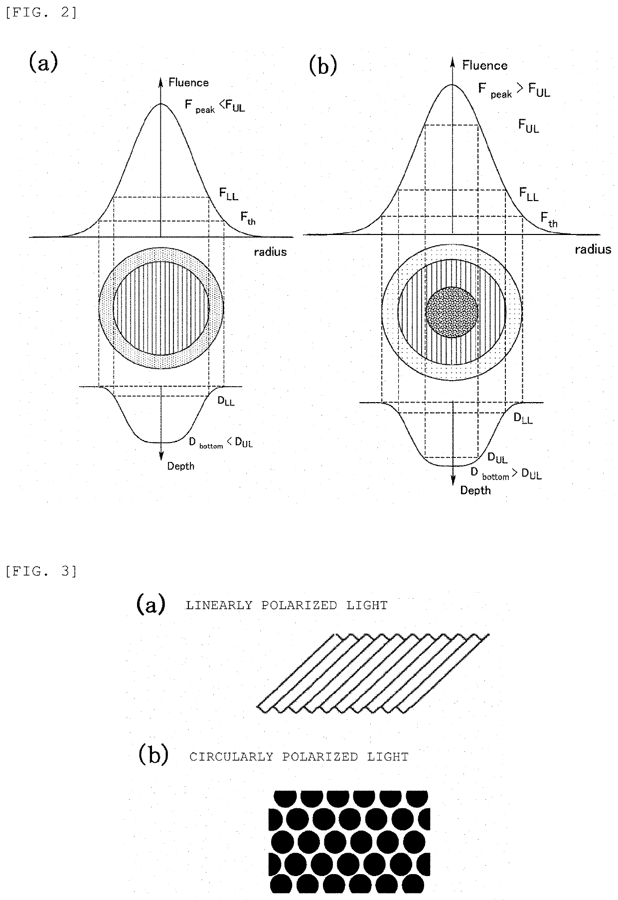
[0030]The present invention has achieved, for the first time, a zirconia-based ceramic having a periodic surface microstructure irregularities of a stripe pattern or a mesh-like raised pattern. Because the microstructure is formed by irradiating an ultrashort pulsed-laser beam, the microstructure can have irregularities of a period about the same as the wavelength of the laser used.
[0031]The zirconia-based ceramic having a surface microstructure of the present invention can be produced using an ultrashort pulsed-laser beam under appropriate conditions, and the surface is free from the adverse effect of heat, or the influence of impurity doping.
[0032]With the periodic microstructured irregularities, the adhesion for the film attached to the zirconia-based ceramic surface can improve, and the zirconia-based ceramic coated with such a film can have improved mechanical strength and heat resistance, in addition to the mechanical characteristics inherent to the zirconia-based ceramic.
[0033]The periodic microstructured irregularities can be formed over a large area, and a ceramic can be obtained that has a large ratio of a periodic structure region by irradiating a laser beam either continuously or using stamping.
[0034]With the fine irregularities, the zirconia-based ceramic having a periodic microstructure formed by using the method of the present invention can have improved adhesion for a calcium phosphate coating.

Problems solved by technology

Zirconia-based ceramics are not easily machineable because of mechanical characteristics such as toughness, hardness, and abrasion resistance.
However, despite the poor workability, these desirable mechanical characteristics of zirconia-based ceramics have been exploited in biomaterial applications such as dental implants, and substitute bone.
However, zirconia-based ceramics themselves have low compatibility to the body, and a technique that coats a highly biocompatible material such as apatite over the material surface is desired to improve biocompatibility.
However, tetragonal zirconia is inferior to calcium phosphate in terms of tissue conductivity, a property that encourages conduction of natural normal tissue to a material surface at the placement site.

Method used


Image

  • Surface structure forming method for zirconia-based ceramics, and zirconia-based ceramics
  • Surface structure forming method for zirconia-based ceramics, and zirconia-based ceramics
  • Surface structure forming method for zirconia-based ceramics, and zirconia-based ceramics

Examples


first embodiment

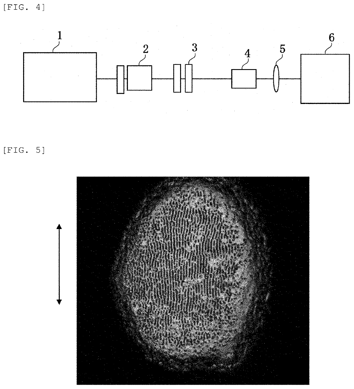
[0080]The present embodiment is described below with reference to FIGS. 4 and 5. FIG. 4 is a schematic diagram showing a laser surface-processing device used in the present embodiment. The device shown in FIG. 4 includes a laser source 1, a power control unit 2, a polarization control unit 3, a beam shaping unit 4, a condensing lens 5, and an irradiation stage 6. The power control unit 2 controls the power of a laser beam (unit: W), or the energy per pulse of a laser beam (unit: J). The polarization control unit 3 controls the direction of polarization of a laser beam and the state of the polarization, more specifically, linearly polarized light, elliptically polarized light, or circularly polarized light. The beam shaping unit 4 controls the beam shape, the intensity distribution inside of a beam, and the beam propagation direction. The irradiation stage 6 is a stage where a workpiece is mounted, and that is freely movable between positions (x, y, z, θ, ϕ) relative to a laser beam....

second embodiment

[0087]A laser source different from that used in First Embodiment was used in the present embodiment. Irradiating a linearly polarized laser beam (Yb-doped KGW (KGd(WO4)2; a wavelength of 1.03 microns, a pulse width of 200 fs) on a zirconia-based ceramic surface formed a periodic microstructured irregularities of a parallel stripe pattern on the surface. The laser beam was irradiated 50 shots. The direction of polarization of the linearly polarized laser beam was parallel to the stripes. The periodic structure had a period of about 1.05 μm / cycle, on average. The period observed had about the same or a slightly longer than the wavelength of the irradiated laser beam. The surface structure was similar to that obtained in First Embodiment, despite the different laser source.

third embodiment

[0088]The present embodiment is described with reference to FIGS. 6, 7, and 8. The present embodiment describes the optimum conditions for forming the periodic structure, among others.

[0089]The etch rate refers to the depth D of an etched hole per shot of a laser beam. In the embodiment, depth D is the mean value determined by, for example, dividing the depth of a hole by the number of shots, 40, irradiated to form the hole. The unit is nm / shot. Here, the shot in the denominator means that the depth is the average value per unit shot.

[0090]FIG. 6 is a diagram representing the relationship between etch rate and a surface state, for example, the presence or absence of a stripe-pattern surface periodic structure, after 40 shots of a linearly polarized laser beam (TiS; a wavelength of 810 nm, 80 fs). In the figure, the horizontal axis represents the etch rate (unit: nm / shot), and the vertical axis represents the state of a laser spot mark in four levels: “No mark”, “No periodic structur...


PUM

PropertyMeasurementUnit
thicknessaaaaaaaaaa
sizeaaaaaaaaaa
timeaaaaaaaaaa

Abstract

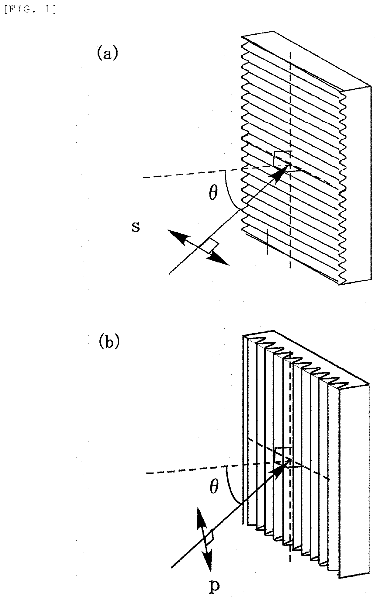
Provided herein is a method for forming a periodic microstructure on a surface of zirconia-based ceramics, which are not easily mechanically workable, without causing thermal adverse effects. A zirconia-based ceramic having a surface periodic microstructure is also provided. A linearly or circularly polarized laser beam is irradiated to a zirconia-based ceramic surface, and periodic irregularities are formed in a spot of the laser beam. Stripe-pattern irregularities parallel to the direction of polarization can be formed in a spot of a laser beam by irradiating a linearly polarized ultrashort pulsed-laser beam to a zirconia-based ceramic surface. A mesh-like raised region and a dot-like recessed region can be periodically formed by irradiating a circularly polarized ultrashort pulsed-laser beam to a ceramic surface.

Description

TECHNICAL FIELD[0001]The present invention relates to a surface structure forming method for fabricating a periodic microstructure on a surface of a zirconia-based ceramic, and to zirconia-based ceramics having a surface periodic structure.BACKGROUND ART[0002]There has been research and development of techniques that form a microstructured irregularities on a material surface. Formation of such a surface microstructure enables improving bonding to the overlying film, and adhesion for liquid, or altering the optical characteristics of the surface.[0003]Zirconia-based ceramics, a material processed in this patent application, are known to have high-strength, and show characteristics that vary with the concentration and the type of additive. A material doped with a predetermined concentration of yttria (yttrium oxide) has toughness, and applications to biomaterials and machine materials are expected. This type of zirconia-based ceramic has also been used for oxygen sensors by taking ad...

Claims


Application Information

Patent Timeline
Patent Type & Authority Patents(United States)
IPC IPC(8): C04B35/48B23K26/352C04B41/91A61F2/30C04B41/00A61C8/00A61C13/00
CPCA61C8/00C04B41/91C04B41/009B23K26/352C04B35/48A61C13/0018A61F2/30A61C8/0012C04B41/0036A61C2008/0046C04B2235/3244C04B2235/963
Inventor KAKEHATA, MASAYUKIYASHIRO, HIDEHIKOMATSUSHIMA, ISAO
Owner NAT INST OF ADVANCED IND SCI & TECH
Learn More