Process for photo-induced partial oxidation of organic chemicals to alcohols, ketones, and aldehydes using flame deposited non-structured photocatalysts

a non-structural, organic chemical technology, applied in the direction of metal/metal-oxide/metal-hydroxide catalyst, energy-based chemical/physical/physical-chemical process, etc., can solve the problems of low energy efficiency, low conversion coefficient, environmental hazardous waste and byproducts, etc., to achieve easy change, increase the amount of cyclohexane conversion or product formation, and the effect of easy chang

Inactive Publication Date: 2002-03-14
U S ENVIRONMENTAL PROTECTION AGCY
View PDF10 Cites 36 Cited by
  • Summary
  • Abstract
  • Description
  • Claims
  • Application Information

AI Technical Summary

Problems solved by technology

The current processes are energy intensive, have low conversion coefficients, and generate environmentally hazardous waste and byproducts.
Although these processes are currently being used, they have low energy efficiencies and generate environmentally hazardous waste and byproducts.
Over-oxidation must be minimized by maintaining conversions low, which is a serious disadvantage from the viewpoint of chemical processing and economics.
Therefore, a major challenge is to find reaction pathways that produce the primary product with high selectivity and at high conversion rates for the hydrocarbons.
Most oxidations are highly exothermic and may generate high localized temperatures and hot spots on the catalyst surfaces, decreasing the service lifetime of the catalyst and resulting in over oxidation of desired products.
Therefore, a major challenge in this field is to find a reaction pathway that affords the primary product with high selectivity and a high conversion rate of the hydrocarbons.
Unfortunately, several commonly used catalysts for oxidation reactions are toxic heavy metals such as chromium and vanadium, or strong acids such as sulfuric acid or nitric acid.
Pollution is inevitable in loading, recovering, and regeneration of these catalysts.
However, most of these processes are low pressure processes and are either not feasible or are too expensive for coating larger areas.
Also, the film composition and other properties cannot readily be varied using these coating methods.

Method used


Image

  • Process for photo-induced partial oxidation of organic chemicals to alcohols, ketones, and aldehydes using flame deposited non-structured photocatalysts
  • Process for photo-induced partial oxidation of organic chemicals to alcohols, ketones, and aldehydes using flame deposited non-structured photocatalysts
  • Process for photo-induced partial oxidation of organic chemicals to alcohols, ketones, and aldehydes using flame deposited non-structured photocatalysts

Examples


example 2

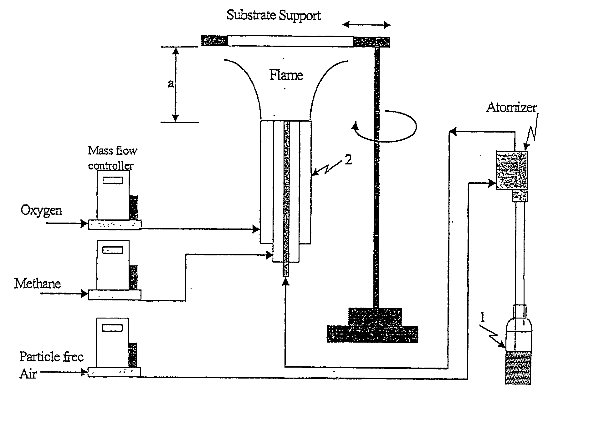
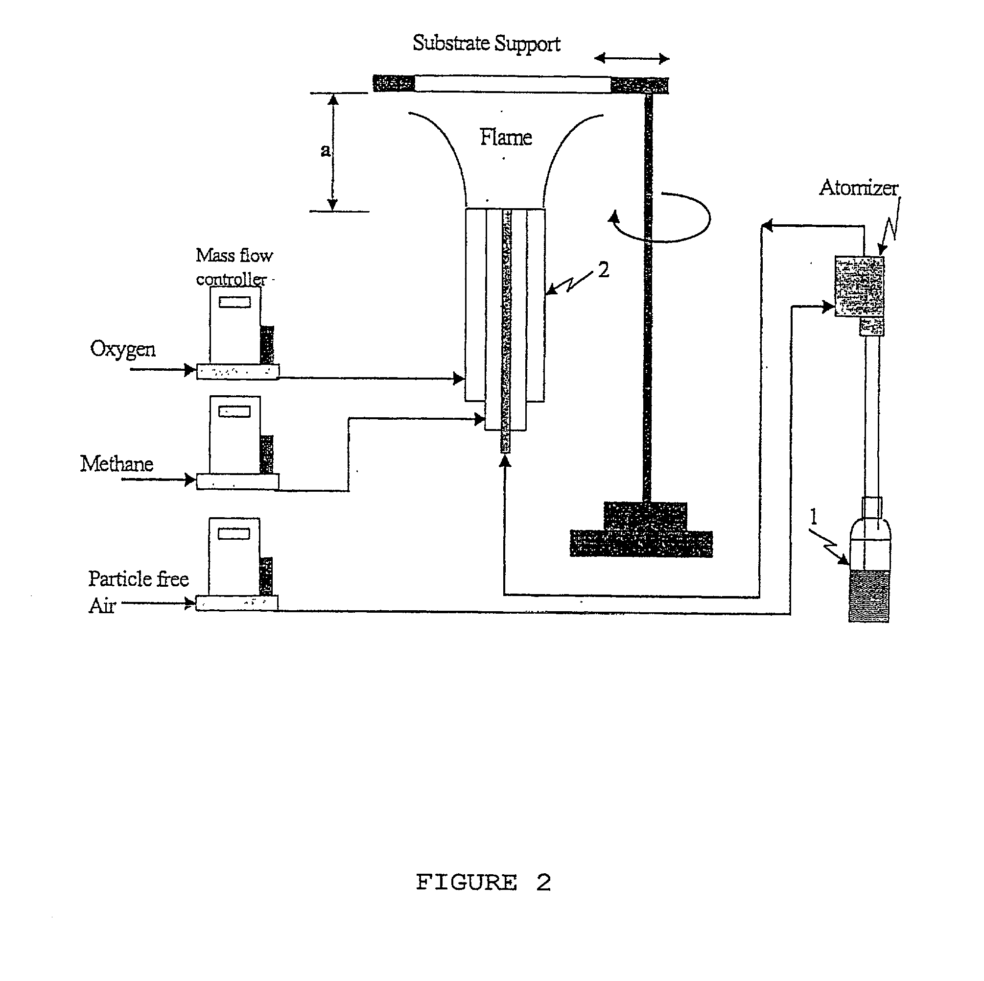
[0084] Different methods of preparing the photocatalyst (dip coating using titanium isopropoxide, commercially available process, sol-gel process and flame aerosol process) were used to deposit the titanium dioxide films (Table 4). Comparing the different catalyst preparation and coating method assists in proving the effectiveness of flame aerosol method. In all cases expect Case 2, the crystal structure of the deposited titanium dioxide was primarily anatase. The flame coated process resulted in more open structures, which allows the penetration of UV light. Flame coating required the smallest mass of titanium dioxide to coat the surface and the smallest primary particle size as determined by transmission electron microscopy.

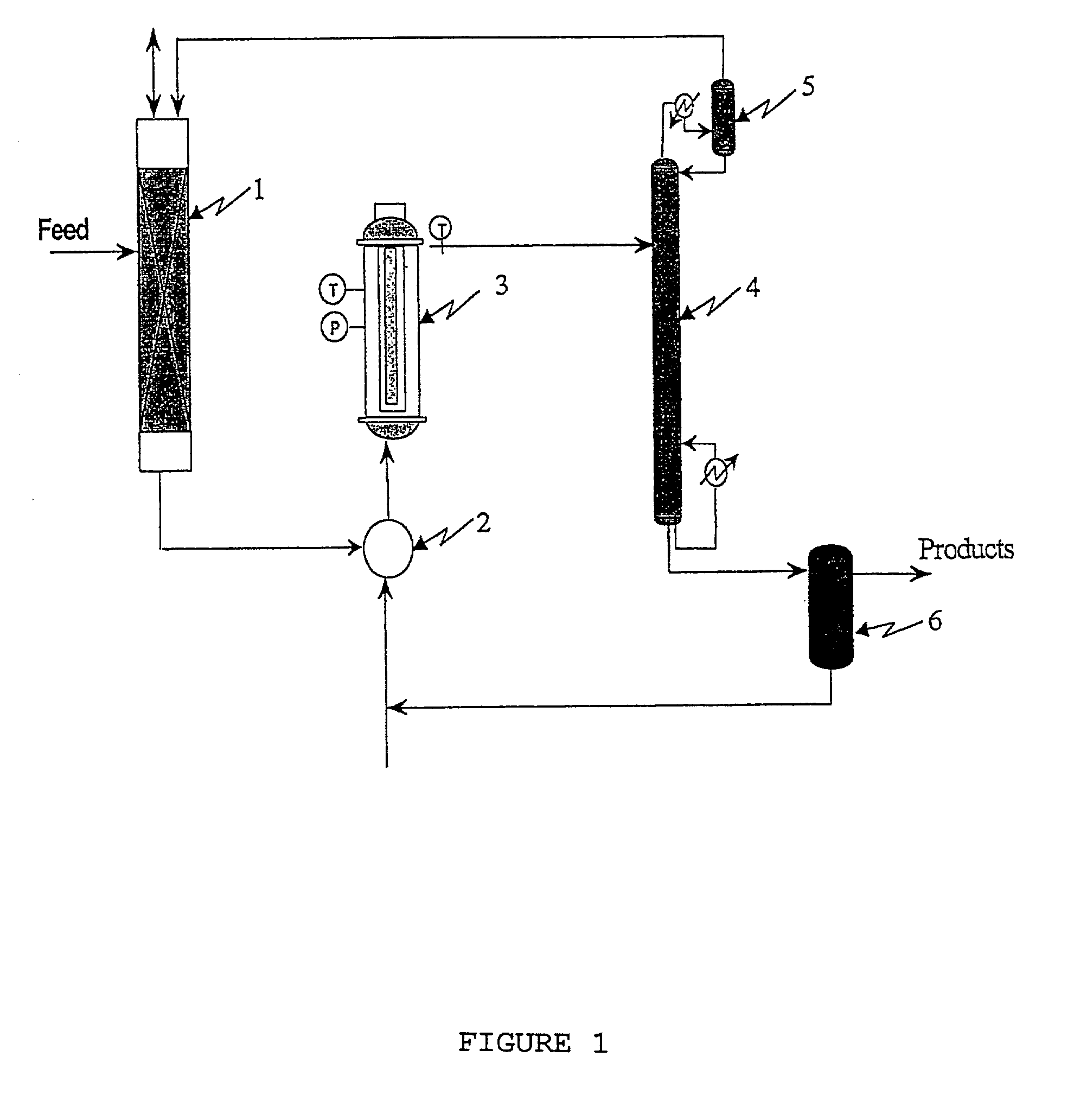
[0085] Two five-hour reaction cycles were used for testing six different films reactors (Table 4). The conversion, yield, reaction selectivity and activity are shown for the different systems. Conversions vary from 1.1 to 8.65 and yield exceeded 96%. The conven...

example 3

[0086] To better establish the role of catalyst the activity of the catalyst was reported as the amount of product formed per gram of catalyst per time. This definition of catalyst is similar to the turnover number per unit mass of catalyst per unit time, and provides a basis for an overall comparison of the different coatings. The activity ranged from 0.013 .mu.mole / (gm.min) for the dip coating method (Case 1) to a high value of 0.969 .mu.mole / (gm.min) for the flame aerosol method (Case 6) (Table 2).

[0087] The flame aerosol coating showed higher effectiveness due to the open structure of the coating and the nanometer size primary particles that creates more electron- hole pairs for the redox reactions. Furthermore, the high specific surface areas resulted in quick desorption of the products, and this minimized coking on the catalyst surface. FIG. 4 illustrates the comparative performance of the thin film reactors prepared by the different coating methodologies. The flame aerosol me...

example 4

[0088] To examine the effect of coking on the catalyst surface, a second five hour testing cycle was used. The activity decreased for most of the films, and a visual browning of the catalyst surface was observed. A similar browning of TiO.sub.2 film was observed by others for the gas phase oxidation of benzene using dry air. The degree of browning (or coking) was greatest for the dip coated films (Case 1 and 2), lesser for the sol-gel films (Case 3) and particularly absent for the flame aerosol coated films (Cases 4, 5 and 6). The minimal coking of the flame aerosol coated films could be due to the presence of solid primary particles (high density, with minimal internal porosity) and the high specific surface areas resulting in quicker desorption of the products (low retentivity on the surface) preventing the formation of higher molecular weight compounds on the surface.

[0089] The flame aerosol coating method enabled the formation of high surface area aggregates with minimal pore ar...


PUM

PropertyMeasurementUnit
temperatureaaaaaaaaaa
mole ratioaaaaaaaaaa
thicknessaaaaaaaaaa

Abstract

Organic molecules are partially oxidized in that the gas phase on supported and immobilized photocatalysts deposited having a nanostructure. the photocatalysts are semiconductors such as titanium dioxide and are preferentially coated onto a substrate by flame aerosol coating.

Description

[0001] CROSS-REFERENCE TO RELATED APPLICATIONS[0002] The present application claims priority from provisional application No. 60 / 218,828, filed Jul. 18, 2000, the entire contents of which are hereby incorporated by reference.[0003] The present invention relates to partial oxidation of organic compounds in the gas phase to produce valuable compounds on supported and immobilized photocatalysts which have been deposited using a flame aerosol coating method.[0004] The cost of handling, treating and disposing of wastes generated annually in the United States has reached as much as 2.2% of the gross domestic product, and continues to rise. The chemical manufacturing industry generates more than 1.5 billion tons of hazardous waste and 9 billion tons of non- hazardous waste annually. Roughly half of the releases and transfers of chemicals reported through the Toxic Release Inventory and 80-90% of hazardous waste generation reported through the Resource Conservation and Recovery Act (RCRA) a...

Claims


Application Information

Patent Timeline
Patent Type & Authority Applications(United States)
IPC IPC(8): B01J12/00B01J19/12B01J21/06B01J35/00C07B41/00C07C29/50C07C45/33C07C45/34C07C45/36C23C16/40C23C16/453
CPCB01J12/007Y10T428/12826B01J21/063B01J35/002B01J35/004B01J2208/00707B01J2219/00045B01J2219/0883B01J2219/0892B01J2219/185B01J2219/1943C07B41/00C07C29/50C07C45/33C07C45/34C07C45/36C23C16/405C23C16/453B01J19/123Y10T428/12528Y10T428/12611Y10T428/12549Y10T428/25Y10T428/12806C07C2101/14C07C49/403C07C33/22C07C35/08C07C31/125C07C31/12C07C31/08C07C31/04C07C2601/14Y10T428/31678Y02P20/52
Inventor SAHLE-DEMESSIE, ENDALKACHEWBISWAS, PRATIMGONZALEZ, MICHALE A.WANG, ZHONG-MINSIKDAR, SUBHAS K.
Owner U S ENVIRONMENTAL PROTECTION AGCY
Why Eureka
Try Eureka