The catalyst of the prior art has a
coating layer of the material of large specific surface area, because the
cordierite carrier of the prior art does not have a specific surface area large enough to carry the required amount of catalyst component.
When the surfaces of the carrier is coated with the material of a large specific surface area, however, the
heat capacity of the carrier increases due to the increase in the
mass, which is undesirable in view of early activation of the catalyst.
The
coating method also has a problem in that the decrease in the opening area of the
cell of the
honeycomb structure leads to an increase in the pressure loss, and the
thermal expansion coefficient becomes larger than that of a carrier which is made solely of cordierite.
However, the ceramic carrier is not practically available because of its short, catalytic life.
It was found that evaporation of the catalyst during operation over a long period of time might decrease the catalyst performance.
It was found that the catalyst described above is more prone to the problem of catalyst evaporation than the catalyst of the prior art which supports the catalyst in pores of .gamma.-
alumina.
Also, it was found that this ceramic carrier is vulnerable to the influence of the exhaust gas, which flows through the cells because the catalyst is supported directly in a multitude of pores which open to the surfaces of the
cell walls, and is therefore more liable to damage caused by catalyst poisoning than the catalyst of the prior art which supports the catalyst in the
porous coating layer.
An
alkali metal or an alkali earth metal used as the
NOx occluding substance is turned into a
sulfate by poisoning with the
sulfur which is included in the exhaust gas and, as a result, it loses the
NOx occluding capacity.
In the three-way catalyst, there is also a possibility that a trace component, which is added as the
promoter, is damaged.
The
oxygen atoms which have been taken into the
crystal make an obstacle for the cordierite unit
crystal lattice to form an orderly structure, thus resulting in the
lattice strain.
The thermal shock temperature difference should be kept within about 900.degree. C. since large cracks make it difficult to maintain the shape of the
honeycomb structure.
When the
amorphous phase or the
crystal phase is unable to endure the thermal stress, microscopic cracks are generated.
When a trace component (
alkali metal element, alkali earth metal element, etc.) included in the
raw material which is believed to contribute to the formation of the
amorphous phase is added in a quantity larger than normal, the number of cracks generated is increased.
While a greater effect of preventing the evaporation can be achieved when a larger portion of the outer surface is covered, it also decreases the permeability of gas thus making it difficult for the exhaust gas to reach the catalyst metal.
Cracks due to thermal shock can be generated when the temperature difference (thermal shock temperature difference) is about 80.degree. C. or larger between the time of heating and after
quenching, while the
crack size increases as the thermal shock temperature difference increases.
The thermal shock temperature difference should be kept within about 900.degree. C. since too large cracks make it difficult to maintain the shape of the
honeycomb structure.
When the
amorphous phase or the crystal phase is unable to endure the thermal stress, microscopic cracks are generated.
When a weak portion of the cordierite structure is unable to endure the
shock wave, microscopic cracks are generated.
Although a
solvent which has large
surface tension such as water does not infiltrate into the pores and is unable to make full use of the pores, a
solvent having smaller
surface tension can infiltrate into microscopic pores.
As a result, when these elements are included in the ceramic by substituting the constituent element of the ceramic which has different value of valence, an imbalance is caused in the
oxygen content as the change in the valence is compensated for similarly to the methods {circle over (3)} and {circle over (4)} of forming defects which make the pores described previously, thus resulting in the formation of
oxygen defects or
lattice defects in the crystal lattice.
If sulfur, which becomes a catalyst poison, is included in the exhaust gas, however, there is such a problem that these elements react with the sulfur to form
sulfate thus losing the NOx occluding capacity.
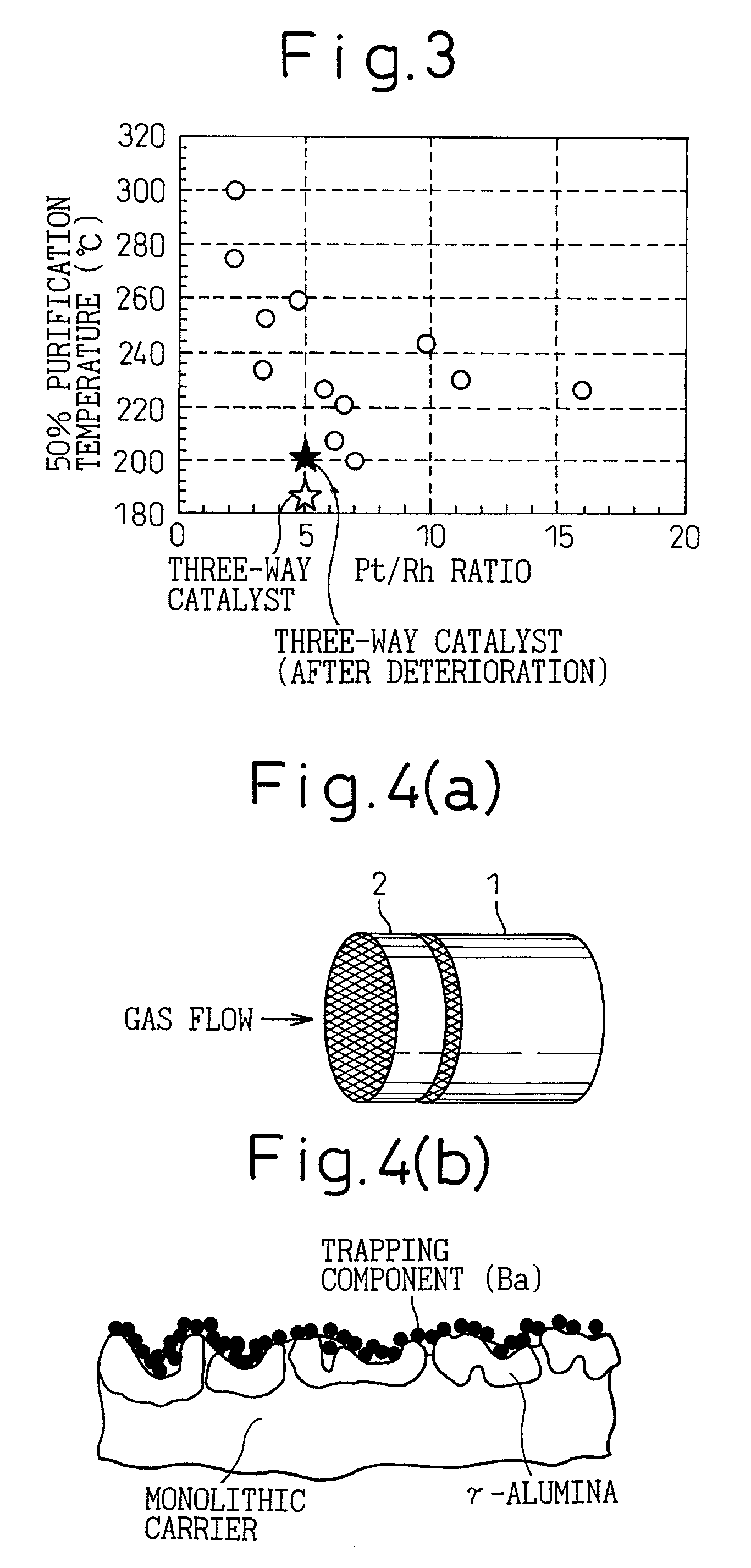
This is because deterioration of the ceramic catalyst body 1 normally leads to a decrease of purification performance by about 20% and a
trapping component of at least 20 mol % is required when it is assumed that the decrease of purification performance is caused solely by catalyst poisoning.
Regeneration by a chemical method which uses heating or chemicals may have adverse influence on the catalytic activity.
Also the coating layer of .gamma.-
alumina can come off when subjected to vibration or
water jet, and this makes it difficult to regenerate.
