
Semiconductor light-emitting element

a technology of light-emitting elements and semiconductors, applied in the direction of basic electric elements, semiconductor devices, electrical equipment, etc., can solve the problems of high cost, difficult to employ white leds for illumination use, and inability to recognize full color by whi

Inactive Publication Date: 2002-08-08
NGK INSULATORS LTD
View PDF0 Cites 27 Cited by
  • Summary
  • Abstract
  • Description
  • Claims
  • Application Information

AI Technical Summary

Benefits of technology

[0023] Accordingly, if a rare earth metal element or a transition metal element is appropriately selected, an any color light, particularly, a white light can be easily obtained by taking advantage of the fluorescent light of the rare earth element or the transition element. In view of easy excitation and easy creation of any color light through the inherent fluorescent light, a rare earth metal element is preferably used.
[0027] For developing the luminescence-recombination probability of electron and electron hole in the island-shaped single crystal portions, it is required that the volume of each of the island-shaped single crystal portions is decreased as small as possible, and the electrons and the electron holes, flown from the outside, are confined in the island-shaped single crystal portions strongly. That is, as the volumes of the island-shaped single crystal portions are decreased, the luminescence probability is increased.
[0028] However, as the volume of the island-shaped single crystal portion is decreased, the surface area thereof is increased, so that the number of the dangling bond of the island-shaped single crystal portion is increased. The carriers of electrons and electron holes are recombined with the dangling bonds in non-luminescence, and thus, the absolute number of carrier to be recombined in luminescence is decreased.
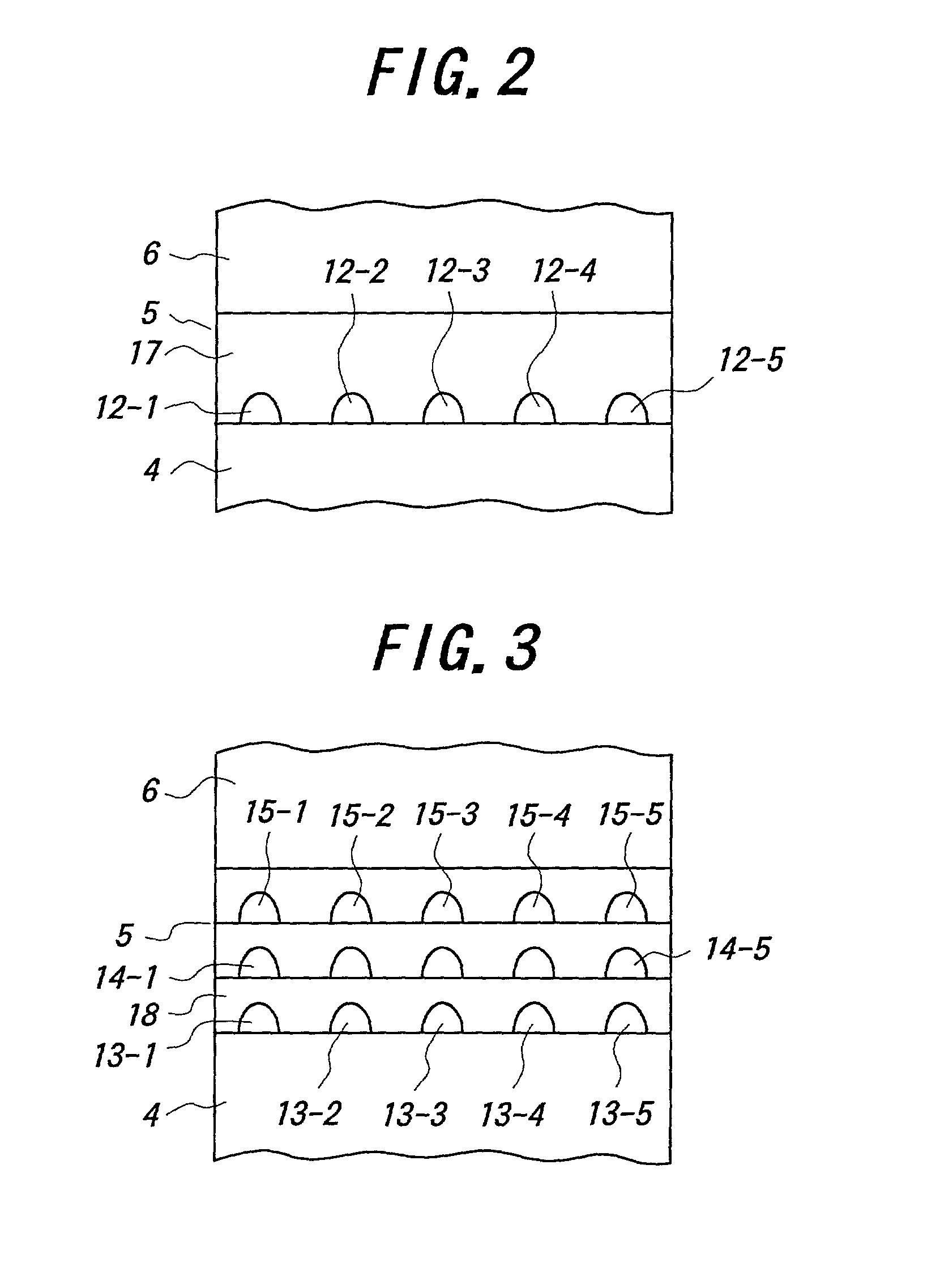
[0029] Therefore, if, according the second semiconductor light-emitting element, a rare earth metal elements and / or a transition metal elements is adsorbed at the boundary between the base layer and the island-shaped single crystal portions and / or the boundary between the base layer and the first cladding layer, and thus, the dangling bonds at the surfaces of the island-shaped single crystal portions are reduced, the recombination in non-luminescence can be reduced and a desired color light can be obtained at a sufficient efficiency.
[0030] The mode of the second semiconductor light-emitting element may be employed in isolation or combination with the mode of the above-mentioned first semiconductor light-emitting element. In the combination case, the fluorescent lights from the rare earth metal element and the transition element can be enhanced, and thus, a desired color light can be easily generated. Also, from the similar reason to the one of the first semiconductor light-emitting element, a rare earth metal element is preferably employed.
[0032] Particularly, if, as adsorbing elements, the same Tm element to generate a blue color wavelength-region light, the same Er element to generate a green color wavelength-region light and the same Eu or Pr element to generate a red color wavelength-region light are employed as the additive elements, a white light can be easily generated at a higher intensity.

Problems solved by technology

However, the white LED using the RGB LED chips requires higher cost because the plural LED chips are employed, so that in view of the cost, it is difficult to employ the white LED for illumination use.
On the other hand, full color can not be recognized by the white LED using the two color lights-emitting diode because it employs only two primary colors, not three primary colors.
In this case, the cost of the white LED is increased because the three primary colors-fluorescent substance is additionally employed for the ultraviolet LED.
However, the luminous efficiency of the resulting ultraviolet LED is largely reduced, as compared with the blue LED.
In this way, the luminous efficiency of the ultraviolet LED is reduced due to the large amount of dislocation in the light-emitting layer, as compared with the blue LED.
However, the ELO technique is a complicated means, so that the manufacturing cost is increased.
Therefore, it is difficult to employ the ELO technique in a practical device manufacturing process, particularly for LEDs.
As of now, however, such a bulky single crystal enough to be applied for the device manufacturing process is not grown and prospected.
However, the GaN single crystal enough to be industrially applied for LEDs has not been fabricated yet.
As a result, the high luminous efficiency in such a white LED as employing three or over primary colors through the illumination of a fluorescent substance by an ultraviolet LED is not technically prospected.
Regardless of the above attempt, however, the semiconductor light-emitting element can not exhibit the practical luminescence intensity and a desired color light, particularly, a white color.

Method used


Image

  • Semiconductor light-emitting element
  • Semiconductor light-emitting element
  • Semiconductor light-emitting element

Examples


example 1

[0071] A sapphire single crystal substrate having a

[0072] diameter of 2 inches and a thickness of 430 .mu.m was employed, and thus, pre-treated by H.sub.2SO.sub.4+H.sub.2O.sub.2, and set into a MOCVD apparatus. To the MOCVD apparatus was attached a gas system of NH.sub.3, TMA, TMG and SiH.sub.4. Then, the substrate was heated to 1200.degree. C., and an ammonia gas (NH.sub.3) was flown with a H.sub.2 carrier gas for five minutes, to nitride the main surface of the substrate. In ESCA analysis, it was turned out that a surface-nitriding layer was formed on the main surface by the surface-nitriding treatment, and the nitrogen content at the depth of 1 nm from the main surface was seven atomic percentages.

[0073] Then, TMA and NH.sub.3 were flown at an average rate of 10 m / sec, with flowing H.sub.2 gas at 10 m / sec, to form an AlN film in a thickness of 1 .mu.m as an underlayer. The full width at half maximum in X-ray rocking curve of the AlN film was 90 seconds, and thus, the good crystal...

example 2

[0081] Except that the island-shaped single crystal portions were formed of Er, Tm, Pr and Eu doped In.sub.0 1Ga.sub.0 9N in a thickness of 20 .ANG. and a diameter of 100 .ANG., and thereafter, Eu, Er, Tm elements were irradiated and adsorbed at the boundary between the island-shaped single crystal portions and the first cladding layer as an underlayer through the molecular beam irradiation from their respective solid raw material sources, a semiconductor light-emitting element was fabricated in the same manner as Example 1.

[0082] Then, when a voltage of 3.5V was applied between the p-type electrode and the n-type electrode and thus, a current of 20 mA was flown through the semiconductor light-emitting element, a white light was generated and emitted from the semiconductor light-emitting element at a luminescence efficiency of 100 lm / W.

[0083] As is apparent from Examples 1 and 2, it is confirmed that the semiconductor light-emitting element of the present invention is usable as a pr...


PUM

PropertyMeasurementUnit
thicknessaaaaaaaaaa
diameteraaaaaaaaaa
thicknessaaaaaaaaaa

Abstract

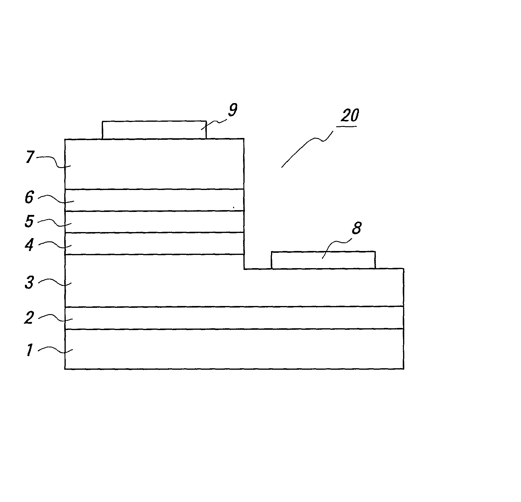
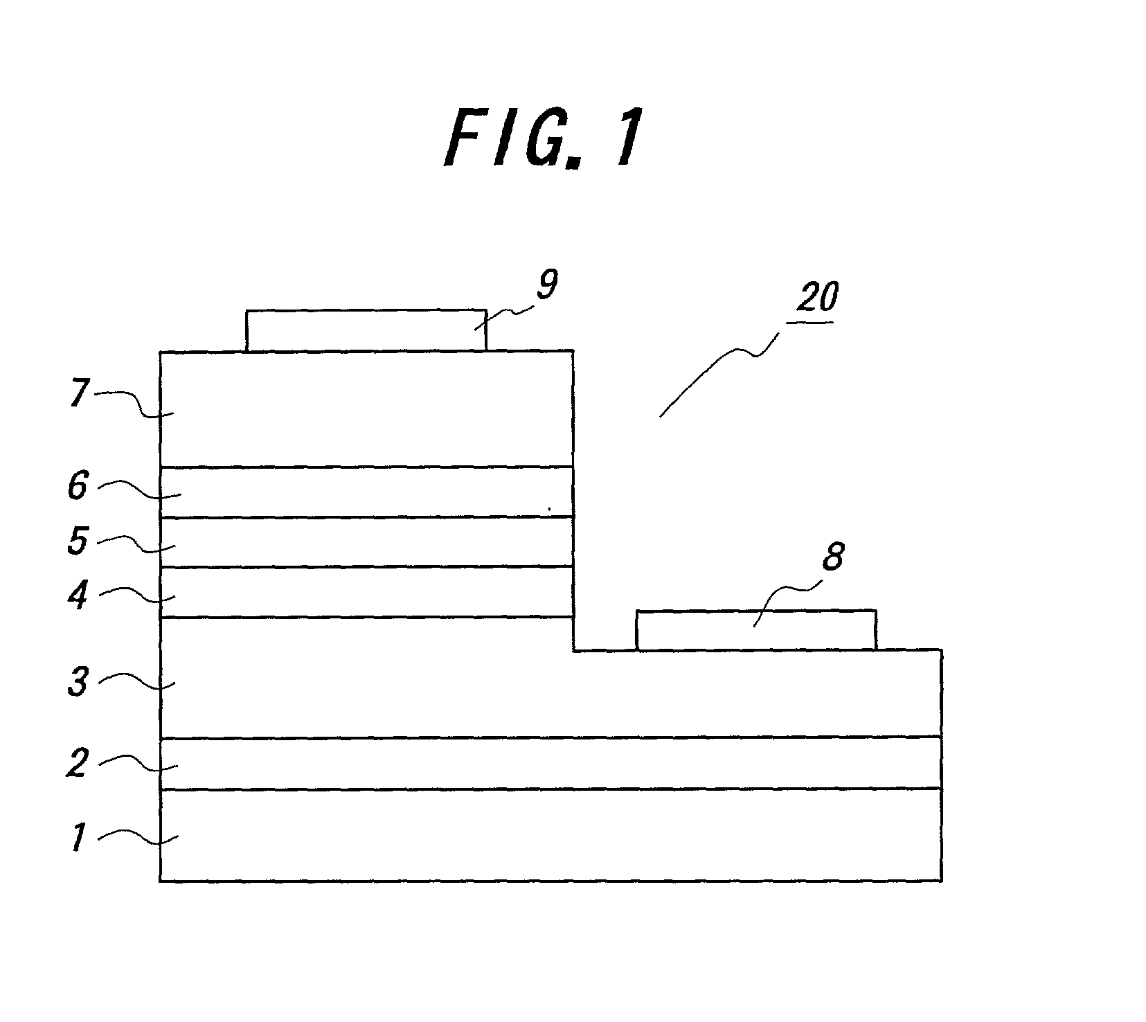
In a semiconductor light-emitting element, an underlayer is made of AlN layer, and a first cladding layer is made of an n-AlGaN layer. A light-emitting layer is composed of a base layer made of i-GaN and plural island-shaped single crystal portions made of i-AlGaInN isolated in the base layer. Then, at least one rare earth metal element is incorporated into the base layer and / or the island-shaped single crystal portions.

Description

[0001] (1) Field of the Invention[0002] This invention relates to a semiconductor light-emitting element, particularly usable for a white light-emitting diode.[0003] (2) Related Art Statement[0004] Recently, various light-emitting diodes (LEDs) are widely available. LEDs are expected for illuminating use as well as displaying use because of their low electric power consumption, long life time, CO.sub.2 gas reduction originated from the reduction of the high energy consumption such as the low electric power consumption, and thus, much demand for the LEDs are expected.[0005] As of now, the LEDs are made of various semi-conducting material such as GaAs-based semi-conducting material, AlGaAs-based semi-conducting material, GaP-based semi-conducting material, GaAsP-based semi-conducting material and InGaAlP-based semi-conducting material, and thus, can emit various color lights from red to yellow-green. Therefore, the LEDs are employed particularly for various displaying use. Recently, b...

Claims


Application Information

Patent Timeline
Patent Type & Authority Applications(United States)
IPC IPC(8): H01L33/32
CPCH01L33/08H01L33/325
Inventor HORI, YUJISHIBATA, TOMOHIKOTANAKA, MITSUHIROODA, OSAMU
Owner NGK INSULATORS LTD
Learn More