Double chamber ion implantation system

a double chamber, ion source technology, applied in the direction of discharge tube/lamp details, light sources, electric discharge tubes, etc., can solve the problems of inefficient beam space charge, ion current constrained by physics limitations, and failure to produce ions of heavy dopant molecules in standard single ion sources,

Inactive Publication Date: 2002-09-12
ENTEGRIS INC
View PDF0 Cites 11 Cited by
  • Summary
  • Abstract
  • Description
  • Claims
  • Application Information

AI Technical Summary

Problems solved by technology

As such, these smaller and thinner requirements challenge the ability of present systems to produce high dose ion beams with the low energy required to implant a high concentration of ions at a shallow depth in the semiconductor device.
However, low energy ion beams that are used for shallow implants, but, for standard dopant atomic ions at low beam energies, have ion currents that are constrained by physics limitations associated with extraction and transport losses.
However, as beam energy decreases to accommodate thinner devices, beam transport of standard ions, defined as dopants, such as boron (B+), arsenic (As+) and phosphorus (P+), becomes inefficient due to beam space charge.
However, attempts to produce ions of heavy dopant molecules in standard single ion sources have generally been unsuccessful.
As such, charge transfer is usually undesirable because it reduces the current density of the desired ion at the desired impact energy.

Method used


Image

  • Double chamber ion implantation system
  • Double chamber ion implantation system
  • Double chamber ion implantation system

Examples


Embodiment Construction

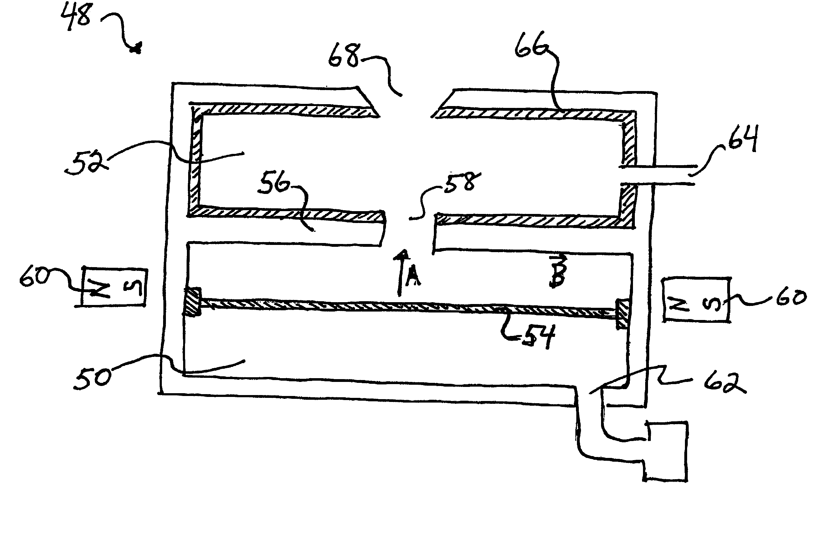
[0041] The present invention provides for a double region ion source to produce a resonant charge exchange between an ion A+ and a neutral heavy molecule, MOL:

A.sup.++MOL A+MOL.sup.+

[0042] The heavy molecules MOL are ionized by charge exchange with the ions A.sup.+. The ions A.sup.+ are first created in a plasma generating region in the ion source of the present invention. The ions A.sup.+ flow into a charge exchange region where electron transfer. As result of charge exchange, molecular ions are produced that are extracted and accelerated to form the output of the improved ion source of the present invention. In the present context, it should be understood that the charge exchange process can create a gas phase ion from any material particle, including atoms, molecules, cluster or any other group of multiple nuclei.

[0043] The ensuing discussion involves the formation of positive ions for implanting, but it should be recognized that similar processes occur for producing negatively c...


PUM


Abstract

An improved double chamber ion source comprising a plasma generating chamber, a charge exchange chamber and a divider structure therebetween. The charge exchange chamber includes magnetic shielding material to reduce exposure of interior components to magnetic field lines externally generated. The double compartment ion source further comprises inclusion of a heat shield and/or a cooling system to overcome deleterious effects caused by increased temperature in the plasma generating chamber. The divider structure has a plurality of apertures having a configuration to reduce surface area on the divider structure in the charge exchange chamber.

Description

[0002] 1. Field of the Invention[0003] The present invention relates to an ion source system, and more particularly, to an improved double chamber ion source that effectively provides heavy gas molecular ions through charge exchange.[0004] 2. Description of the Related Art[0005] Numerous semiconductor manufacturing processes employ ion implantation for forming a p-n junction by adding dopants (impurities), such as boron (B) and phosphorus (P) to a semiconductor substrate. Ion implantation makes it possible to accurately control the concentration and depth of impurities to be diffused into a target spot on the semiconductor substrate.[0006] Typically, an ion implanter includes an ion source that ionizes an atom or molecule of the material to be implanted. The generated ions are accelerated to form an ion beam that is directed toward a target, such as a silicon chip or wafer, and impacts a desired area or pattern on the target. The entire operation is carried out in a high vacuum.[000...

Claims


Application Information

Patent Timeline
Patent Type & Authority Applications(United States)
IPC IPC(8): H01J27/14H01J37/08
CPCH01J37/08H01J2237/31701
Inventor VELLA, MICHAEL C.
Owner ENTEGRIS INC
Why Eureka
Try Eureka