Triphenylamine derivative and organic electroluminescence device comprising the same

a technology of organic electroluminescence and triphenylamine, which is applied in the preparation of amino compounds, natural mineral layered products, instruments, etc., can solve the problems of insufficient stability and durability of organic electroluminescence devices, deterioration of carrier injection efficiency, etc., and achieves improved heat resistance and high hole-transporting capacity.

Inactive Publication Date: 2002-09-12
CHEMIPRO KASEI KAISHA
View PDF0 Cites 17 Cited by
  • Summary
  • Abstract
  • Description
  • Claims
  • Application Information

AI Technical Summary

Benefits of technology

[0035] To solve the foregoing problems, the inventors made extensive studies on the structure of triphenylamine derivative.
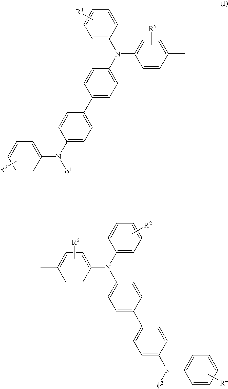
[0036] As a result, it was found that a compound obtained by replacing each one of the respective two phenyl groups connected to a nitrogen atom (N) at both terminals of the foregoing TPTE, i.e., two phenyl groups in total, by a naphthyl ring or higher aromatic condensed ring as shown in the following general formula (1): 7
[0037] wherein R.sup.1, R.sup.2, R.sup.3, R4, R.sup.5 and R.sup.6 may be the same or different and each represents a hydrogen atom, alkyl group, halogenated alkyl group, aryl group, dialkylamino group or cyano group; and .phi..sup.1 and .phi..sup.2 may be the same or different and each represents an aromatic condensed ring which may have a substituent, has the following advantages:
[0038] (1) The compound has a glass transition temperature Tg of not lower than about 140.degree. C. and hence has a drastically improved heat resistance while maintaining the high hole-transporting capacity inherent to TPTE; and
[0039] (2) The compound hardly forms an exciplex assumingly because of its stereostructure having substituted large aromatic condensed rings at its terminals or because of the distribution of .pi. electron conjugated system.

Problems solved by technology

However, the conventional organic electroluminescence devices are disadvantageous in that they exhibit insufficient stability and durability mainly attributed to (1) deterioration of organic compound itself due to Joule's heat developed when the device is energized or (2) deterioration in the carrier injection efficiency between various layers due to the reduction in smoothness of interface caused by the crystallization of organic compound by Joule's heat thus developed, and hence exhibit a drastically reduced luminance during a repeated use.
In particular, these compounds cannot satisfy the high heat resistance required for on vehicle display devices.
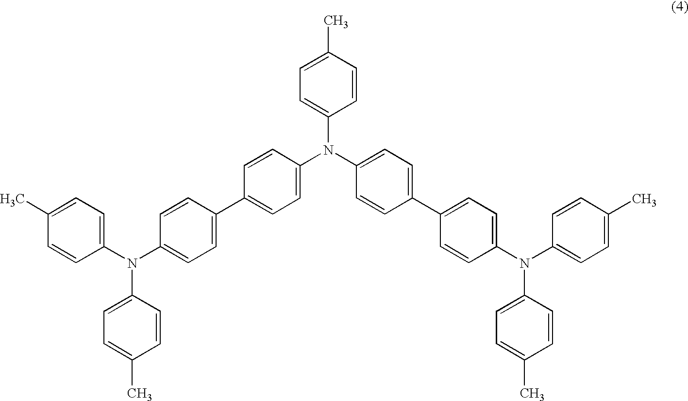
However, HTM1 (a trimer of triphenylamine) represented by the foregoing formula (4) exhibits a glass transition temperature Tg of about 110.degree. C. and hence shows a difference as small as 25.degree. C. from the foregoing ambient temperature, demonstrating that it exhibits an insufficient heat resistance.
Thus, if continuously operated at such a high temperature and humidity, the foregoing generation of Joule's heat causes the temperature of the device itself to exceed the glass transition temperature Tg of HTM1 in an extremely short period of time, resulting in deterioration of the foregoing organic compound itself, i.e., HTM1 itself, or reduction in the injection efficiency between layers.
Thus, if there is some dispersion of thickness, current is concentrated into the section having the smallest thickness to cause local rise in temperature, resulting in the cracking and peeling of the organic layers that cause short-circuiting between the cathode and the anode.
It is thus expected that a device comprising HTM1 shows a drastic drop in luminance or stops light emission in a short period of time due to the foregoing defects.
C. Thus, if continuously operated at such a high temperature and humidity, it can be expected that the resulting deterioration of TPTE itself or the injection efficiency between layers or the short-circuiting between the cathode and the anode causes the device to show a drastic drop of luminance or to stop light emission in a short period of ti
Thus, the temperature at which the device can stably and continuously emit light over an extended period of time was not confirmed therein.
According to the inventors' study, the organic electroluminescence device comprising TPTE is disadvantageous in that it exhibits too small an external quantum efficiency to emit light with a high luminance at a small current.
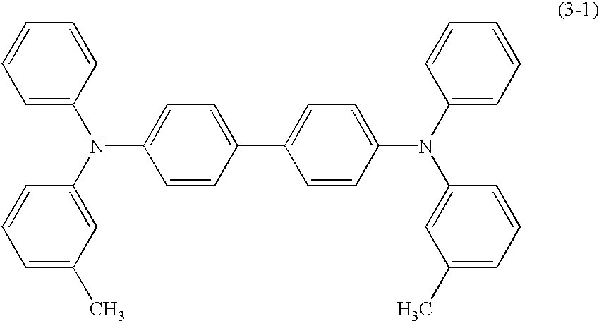
However, the foregoing meta-position-linkage TPTE (hereinafter referred to as "m-TPTE") is disadvantageous in that it exhibits a glass transition temperature as low as about 90.degree. C. and thus cannot be used for the purpose requiring a high heat resistance and reliability as in the foregoing on vehicle display device.

Method used


Image

  • Triphenylamine derivative and organic electroluminescence device comprising the same
  • Triphenylamine derivative and organic electroluminescence device comprising the same
  • Triphenylamine derivative and organic electroluminescence device comprising the same

Examples


synthesis example 1

[0129] A suspension obtained by adding to 50 ml of decalin 15.0 g (68.4 mmol) of N-phenyl-N-(2-naphthyl)amine, 27.8 g (68.40 mmol) of 4,4'-diodobiphenyl represented by the formula (1b), 18.9 g (136.81 mmol) of potassium carbonate and 0.9 g (13.68 mmol) of copper powder was heated to a 200.degree. C. with stirring in a stream of argon to undergo reaction for 4 days.

[0130] To the reaction solution were then added 4.7 g (34.20 mmol) of potassium carbonate and 0.9 g (13.68 mmol) of copper powder. The reaction solution was then allowed to undergo reaction under the same conditions for 4 days.

[0131] The reaction solution was then filtered while being kept at the high temperature to remove insoluble matters therefrom. The filtrate was then washed with toluene.

[0132] The filtrate was allowed to cool, again filtered to remove 4,4'-diodobiphenyl therefrom, washed with ethyl acetate, and then subjected to distillation under reduced pressure to remove the solvent therefrom.

[0133] The residue wa...

synthesis example 2

[0143] 70.2 g of 4-(N-phenyl-N-(2-naphthyl))amino-4'-iodobiphenyl represented by the foregoing formula (1c) synthesized in the same manner as in Synthesis Example 1 and 12.0 g (56.53 mmol) of 3,3'-dimethylbenzidine represented by the following formula (1e): 25

[0144] were allowed to undergo reaction in the presence of 27.3 g (197.84 mmol) of potassium carbonate and 1.1 g (16.96 mmol) of copper powder in decalin at a temperature of 140.degree. C. for days. The reaction product was then column-purified with 1 kg of silica gel to obtain N,N'-bis(N-phenyl-N-(2-naphthyl)-4'-aminobiphenyl-4-il)-1,1'-biphenyl-3,3- '-dimethyl-4,4'-diamine represented by the following formula (1f). 26

[0145] 21.4 g (22.50 mmol) of N,N'-bis(N-phenyl-N-(2-naphthyl)-4'-aminobip- henyl-4-il)-1,1'-biphenyl-3,3'-dimethyl-4,4'-diamine thus obtained and 10.1 g (49.49 mmol) of iodobenzene represented by the following formula (1g): 27

[0146] were then allowed to undergo reaction in the presence of 27.3 g (197.84 mmol) of...

example 1

[0155] A glass substrate with a size of 25 mm long.times.25 mm wide.times.1 mm thick having an ITO electrically-conductive transparent layer formed by sputtering process on one side thereof as an anode was supersonically cleaned sequentially with a surface active agent and an organic solvent, and then subjected to ultraviolet ozone treatment so that it was cleaned.

[0156] Subsequently, the foregoing glass substrate was placed in a vacuum evaporation apparatus where the following various layers were then sequentially deposited on the surface thereof by vacuum evaporation method at a pressure of from 10.sup.-6 to 10.sup.-7 torr.

[0157] (1) A hole-transporting layer having a thickness of 60 nm formed by vacuum-evaporating NPTE-1 synthesized in Synthesis Example 1 as a hole-transporting material from a quartz crucible disposed in the vacuum evaporation apparatus by resistance heating method;

[0158] (2) An electron-transporting layer having a thickness of 60 nm formed by vacuum-evaporating ...


PUM

PropertyMeasurementUnit
RHaaaaaaaaaa
temperatureaaaaaaaaaa

Abstract

A triphenylamine derivative represented by the following general formula (1): 1 wherein R.sup.1, R.sup.2, R.sup.3, R.sup.4, R.sup.5 and R.sup.6 may be the same or different and each represents a hydrogen atom, alkyl group, halogenated alkyl group, aryl group, dialkylamino group or cyano group; and .phi..sup.1 and .phi..sup.2 may be the same or different and each represents an aromatic condensed ring which may have a substituent. Also disclosed is an electroluminescence device comprising the triphenylamine derivative.

Description

FIELD OF THE INVENTION[0001] The present invention relates to a novel triphenylamine derivative which can be preferably used as a hole-transporting material, e.g., for organic electroluminescence device and an organic electroluminescence device comprising the same.BACKGROUND OF THE INVENTION[0002] As an organic electroluminescence device comprising an organic layer mainly comprising an organic compound provided interposed between a pair of electrodes, i.e., cathode and anode there had been generally used one comprising a single organic layer. In recent years, however, various organic electroluminescence devices comprising a plurality of organic layers each independently having a function such as emission of light and transportation of carrier (e.g., hole, electron) (as disclosed in C. W. Tang and S. A. VanSlyke, "Appl. Phys. Lett.", 51, 913 (1987), C. Adachi, T. Tsutsui and S. Saito, "Appl. Phys. Lett.", 55, 1489 (1989), J. Kido, M. Kimura, and K. Nagai, "Science", Vol. 267, 1332 (1...

Claims


Application Information

Patent Timeline
Patent Type & Authority Applications(United States)
IPC IPC(8): C07C211/54C09K11/06G03G5/06C07C211/58H01L51/30H01L51/50H05B33/12
CPCC09K11/06H01L51/0059H01L51/006H01L51/0081H01L51/5012H01L2251/308H10K85/631H10K85/633H10K85/324H10K50/11H10K2102/103C07C211/54H10K50/00
Inventor UEMURA, TAKASHIOKUDA, NOBUYUKIUEBA, YOSHINOBU
Owner CHEMIPRO KASEI KAISHA
Why Eureka
Try Eureka