Lens manufacturing process

a manufacturing process and lens technology, applied in the field of lens manufacturing process, can solve the problems of low overall yield, low quality, low cost, etc., and achieve the effects of high overall yield, high automation, and desirable physical qualities

Inactive Publication Date: 2002-10-24
NOVARTIS AG
View PDF53 Cites 31 Cited by
  • Summary
  • Abstract
  • Description
  • Claims
  • Application Information

AI Technical Summary

Benefits of technology

0006] Accordingly, there is room for improvement in developing suitable processes to make lenses from new polymers with improved properties. Attempts have been made to use injection molding processes to make ophthalmic lenses from polymethylmethacrylate (PMMA). PMMA lenses are hard and not oxygen permeable, i.e., they do not compare to the quality of softer hydrogel lenses. Thus, while injection molded processes, such as typically used in the plastics industry, are capable of high-speed, high-volume, consistent-quality mass production, there have not been good ophthalmic lens materials that possess the desirable properties for ophthalmic lenses that could take advantage of those plastics manufacturing processes.
0007] Although soft hydrogel polymers have more desirable qualities for ophthalmic lenses than does PMMA, conventional soft hydrogel ophthalmic lenses are made from crosslinked hydrophilic polymers that cannot be prepared in large batches and later be melt processed in standard molding equipment. Because of the difficulties in processing crosslinked polymers, there is a need for a process that uses thermoformable or melt processable polymers that can be made in large batches of a consistent quality, to be used in high speed, high volume molding equipment to make a soft ophthalmic lens with desirable physical qualities. Such a process can also offer advantages in the form of reusable molds, high overall yield, off-line main chemistry such that the reaction in the mold includes the final crosslinking. It is desirable that the process is highly automated and integrated. Such a process would be useful for soft ophthalmic lens manufacturing, but could also be used for any small optical object, and small plastic object. The present invention addresses these needs, and also provides other advantages as will be evident from the following description.
0008] In one embodiment of the invention, a method is provided for molding an ophthalmic lens comprising: providing a first mold part having a front curve molding surface for the ophthalmic lens; providing a second mold part having a back curve molding surface for the ophthalmic lens; depositing an amount of a melt-processable polymer in the first mold part; pressing together the first mold part with the second mold part, the mold parts thereby forming a mold cavity between the opposing front curve molding surface and back curve molding surface with the polymer therebetween, the mold cavity defining a shape of an ophthalmic lens having a variable volume at least between a first volume and a second volume, the second volume being greater than the first volume, and the amount of polymer having a volume between the first volume and the second volume, wherein the mold parts have sufficiently small clearance such that gas escapes from the mold cavity and none of the polymer escapes from the mold cavity; allowing the polymer to solidify and form a lens; opening the mold; and removing the lens from the mold.
0009] In a second embodiment of the invention, a method is provided for making a soft ophthalmic lens comprising: providing a first mold part having a front curve molding surface for the ophthalmic lens; providing a second mold part having a back curve molding surface for the ophthalmic lens, the mold parts adapted to mate together to form a mold cavity in the shape of an ophthalmic lens having a variable volume at least between a first volume and a second volume, the second volume being greater than the first volume; extruding a melt-processable polymer, the polymer having a glass transition temperature (T.sub.g), a flow temp...

Problems solved by technology

Various materials have been utilized in making contact lenses, but these materials have been found less than ideal.
Lathing is not able to meet demands of low-cost, high-volume, high-yield rapid production.
This process is less costly than lathing, but not as inexpensive as a complete cast molding process.
Spin-casting, on the other hand, often results in lenses with optical quality and fitting problems because the back surface of the lens is determined by centrifugal force and not the requirements of an optimized lens mold design.
These molds are often disposable, and the cost to replace the mold for each new lens is a significant part of the total cost of the final lens.
Furthermore, lenses made by cast molding also suffer a large number of quality defects during in situ polymerization due to shrinkage.
For example, shrinkage may cause surface voids and the non-adherence of the final product to the lens design.
How...

Method used


Image

  • Lens manufacturing process
  • Lens manufacturing process
  • Lens manufacturing process

Examples


example no.1

Example No. 1

[0128] A thermoplastic material was used which had been made as follows. To a 500-mL four-neck cylinder flask, equipped with mechanical stirring, reflux condenser, and nitrogen inlet, was charged toluene (180 .mu.L), DMA (64.7 wt %), FX-13 (20 wt %), and DPMS-MA (15 wt %) with Vazo64 (0.3 wt %). The total mass of monomers was 30 g. The solution was purged with nitrogen for 10 minutes, and then was polymerized with thermal initiation at 60 .degree. C. for 20 hours. The polymer was characterized as having a T.sub.g of 104.degree. C. and a weight average molecular weight of 118,000.

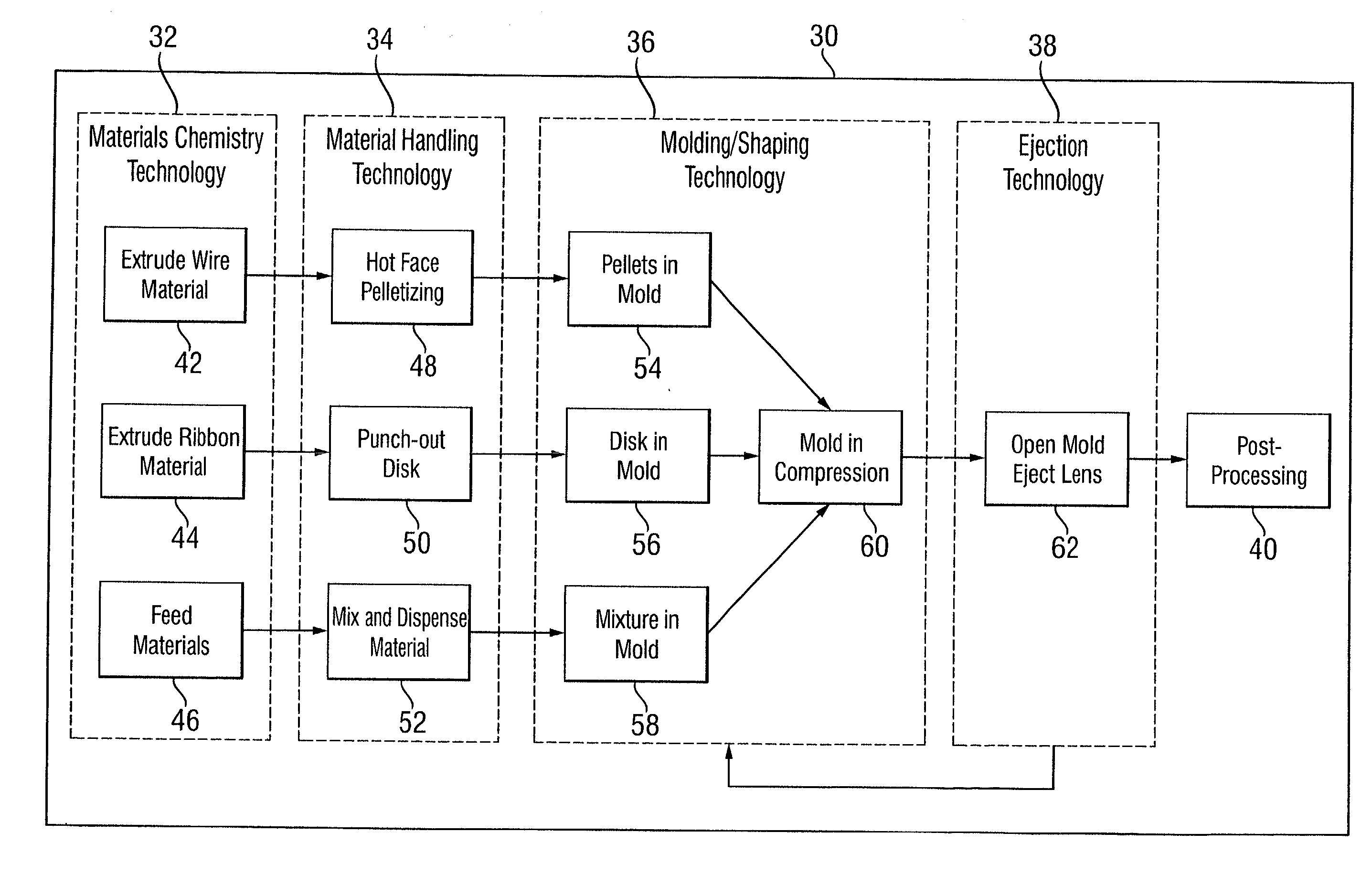
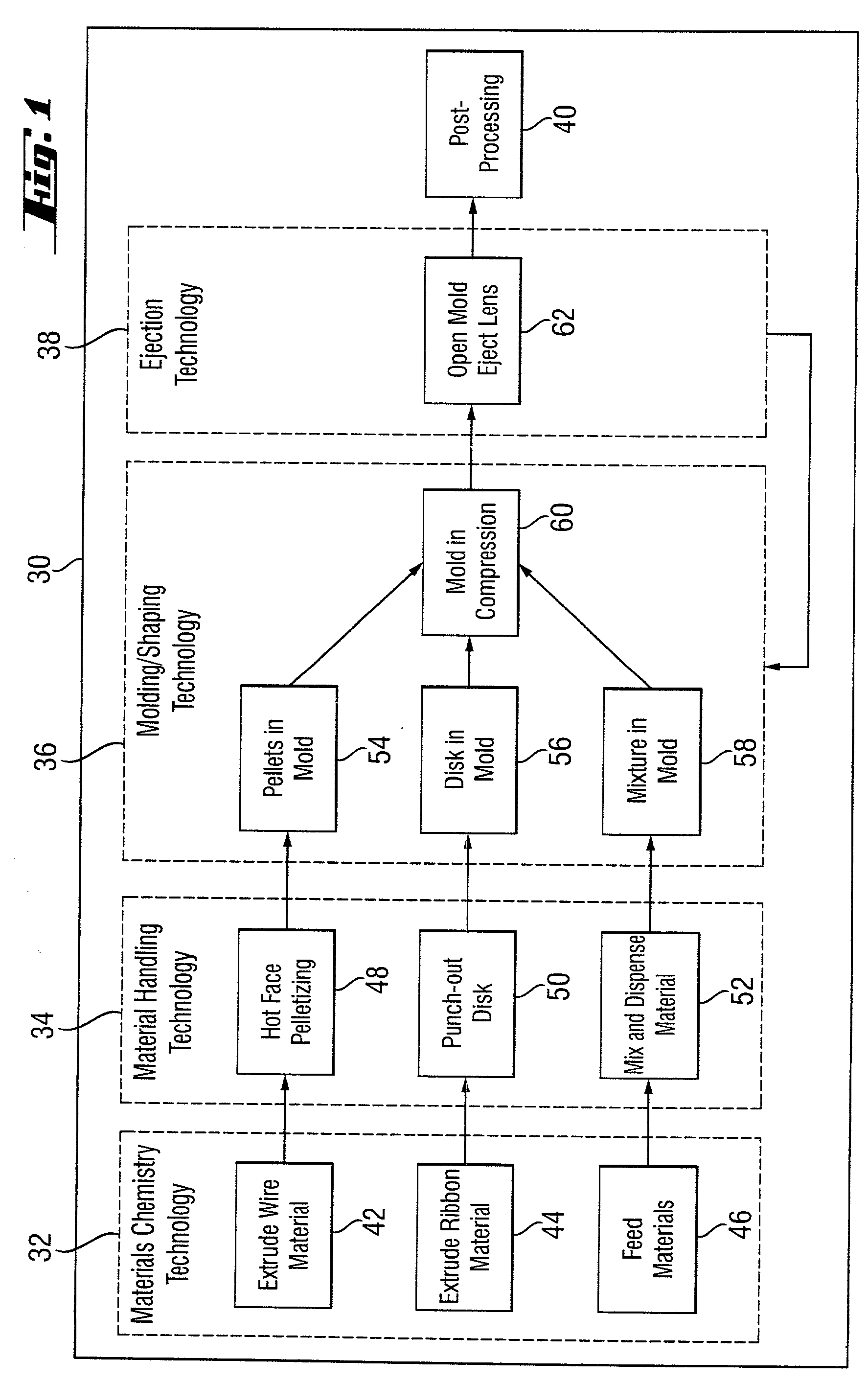
[0129] The thermoplastic material was held in a compression mold similar to those illustrated in FIGS. 14-17, having a mold cavity diameter of 14 mm. The temperature of the mold was 175.degree. C., and the applied force was 2 tons. The mold was opened after 5 minutes, with the lens-like object adhered to the base curve. Hydration of the object for 5 minutes produced a contact lens.

example no.2

Example No. 2

[0130] A thermoplastic material was used which had been made as described in Example 1, except using the following monomer proportions: DMA (49.7 wt %), FX-1 3 (20 wt %), and DPMS-MA (30 wt %). The polymer was characterized as having a T.sub.g of 95.degree. C. and a weight average molecular weight of 149,000.

[0131] The thermoplastic material was held in a compression mold having a mold cavity diameter of 14 mm. The temperature of the mold was 175.degree. C., and the material was softened in the mold for 5 minutes. A force of 1 ton was applied for 6 minutes, followed by hydration of the object for 5 minutes to produce a contact lens.

example no.3

Example No. 3

[0132] A thermoplastic material was used which had been made as follows. To a 500-mL four-neck cylinder flask, equipped with mechanical stirring, reflux condenser, and nitrogen inlet, was charged toluene (150 mL), dimethylacrylamide (DMA) (54.5 wt %), FX-13 (20.0 wt %), DPMS-MA (15.0 wt %), and PEGME-MA (10 wt %) with Vazo52 (0.5 wt %). The total mass of monomers was 30 g. The solution was purged with nitrogen for 20 minutes, and then was polymerized with thermal initiation at 45.degree. C. for 20 hours. The branch copolymer was collected and dried. The polymer was characterized as having a T.sub.g of 65 .degree. C. and a weight average molecular weight of 190,000.

[0133] The thermoplastic material (20 mg) was held in a compression mold having a mold cavity diameter of 10 mm. The temperature of the mold was 150.degree. C., and the material was softened in the mold for 30 minutes. The mold was closed, but no force was applied for 5 minutes. A force of 0.2 metric ton was t...


PUM

PropertyMeasurementUnit
Fractionaaaaaaaaaa
Fractionaaaaaaaaaa
Timeaaaaaaaaaa

Abstract

A process for manufacturing ophthalmic lenses is described. This process has several phases, including raw material processing, material metering and dispensing, the material shaping, and ejection/de-molding. The material-shaping phase can utilize various molding processes including compression molding, thermoforming, reaction injection molding, or injection molding. The process allows re-use of the shaping molds/dies and can be automated.

Description

[0001] This invention relates to the preparation of ophthalmic devices through a molding process. More particularly, the invention relates to ophthalmic lenses, such as contact lenses and intraocular lenses, made by the molding of polymers.[0002] The use of contact lenses as corrective ophthalmic devices, as well as for cosmetic purposes, is well known. Various materials have been utilized in making contact lenses, but these materials have been found less than ideal.[0003] Historically, contact lenses have been manufactured by one of the three processes: lathing, spin-casting, and cast molding. Lathing is not able to meet demands of low-cost, high-volume, high-yield rapid production. Efforts to reduce the inherent cost disadvantages of lathing have produced a process that is a hybrid of lathing and cast molding. For example, lenses may be prepared by casting one side of the lens and lathing the other side. This process is less costly than lathing, but not as inexpensive as a complet...

Claims


Application Information

Patent Timeline
IPC IPC(8): G02C7/04B29B9/06B29B11/10B29C43/02B29C43/34B29C43/36B29D11/00B29L11/00G02B3/00
CPCB29C43/34B29C43/36B29C43/361B29L2011/0041B29D11/00009B29K2105/251B29L2011/0016B29C2043/3433
Inventor GOBRON, STEPHANEROVANI, WILLIAM
Owner NOVARTIS AG
Why Eureka
Try Eureka