Epoxy resin compositions, solid state devices encapsulated therewith and method

a technology of epoxy resin and composition, applied in the direction of plastic/resin/waxes insulators, semiconductor/solid-state device details, display means, etc., can solve the problems of poor thermal aging stability, common packaging materials often undergo a gradual loss of optical and mechanical properties, and devices often exhibit special packaging needs, etc., to achieve better match between the two refractive indexes, increase the amount of light emitted, and increase the refractive index

Inactive Publication Date: 2003-04-17
GENERAL ELECTRIC CO
View PDF0 Cites 88 Cited by
  • Summary
  • Abstract
  • Description
  • Claims
  • Application Information

AI Technical Summary

Benefits of technology

0035] Optional components in the present invention also comprise refractive index modifiers. As light passes from the relatively high index of diffraction chip (typically 2.8-3.2) to the lower refractive index epoxy encapsulant (typically 1.2-1.6) some of the light is reflected back to the chip at the critical angle. Modifiers with high refractive index added to the epoxy increase its refractive index, producing a better match of the two refractive indices and an increase in the amount of emitted light. Such materials increase the refractive index of the epoxy without significantly affecting the transparency of the epoxy encapsulant. Modifiers of this type comprise additives with high refractive index. These materials comprise optically transparent organics or inorganics, and agglomerates of particles or structures whose size is less than the size of the wavelengt

Problems solved by technology

Such devices often exhibit special packaging needs.
Common packaging materials will often undergo a gradual loss of optical and mechanical properties due to the combination of thermal, oxidative and photodegradation processes.
As described in U.S. Pat. No. 4,178,274, to Denk et al., one disadvantage of these compositions, which harden fast through the use of known accelerators such as tertiary amines, imidazoles or boron trifluoride complexes, is their poor thermal aging stability.
Furthermore, because of the aromatic character of bisphenol-A based epoxy resins, these encapsulants are typically less stable to ultraviole

Method used


Image

  • Epoxy resin compositions, solid state devices encapsulated therewith and method
  • Epoxy resin compositions, solid state devices encapsulated therewith and method
  • Epoxy resin compositions, solid state devices encapsulated therewith and method

Examples


Embodiment Construction

1-3

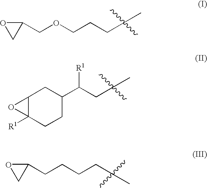
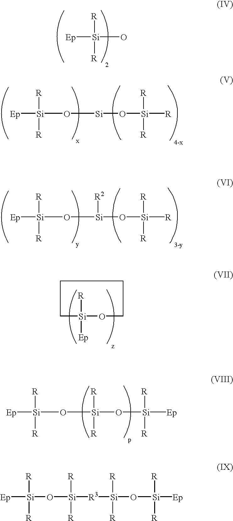
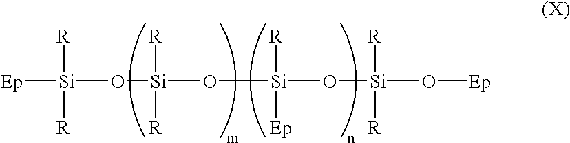
[0039] Epoxy resin encapsulants were prepared by combining the various epoxy-comprising resins, curing agents and other components as shown in Table 1, and curing under the specified conditions. All quantities are in parts by weight. The abbreviation "RT" means room temperature. The composition of Example 3 also contained 0.08 wt. % of a hindered phenol stabilizer and 0.08 wt. % of a phosphite stabilizer. 1,1,3,3-Tetramethyl-1,3-bis[2(7-oxabicyclo[4.1.0]hept-3-yl)ethyl]disiloxa-ne was employed as silicone epoxy resin. The hydroxyl-containing compound (B) was a hydroxyl-containing silicone resin comprising the hydrolysis product of a mixture of phenyltrichlorosilane, methyltrichlorosilane, and dimethyldichlorosilane.

1TABLE 1 Component Ex. 1 Ex. 2 Ex. 3 Component A epoxy resin 3,4-epoxycyclohexylmethyl-3,4-73 28.9 --epoxycyclohexanecarboxylate (ERL 4221D) bisphenol-A diglycidyl ether oligomer -- 36.2 --(EPON 828) silicone epoxy resin -- -- 78.38 Component B hydroxyl-containing sili...


PUM

PropertyMeasurementUnit
Percent by massaaaaaaaaaa

Abstract

Epoxy resin compositions are disclosed which comprise (A) at least one silicone epoxy resin, (B) at least one hydroxyl-containing compound, (C) at least one anhydride curing agent, (D) at least one ancillary curing catalyst, and optionally at least one of thermal stabilizers, UV stabilizers, cure modifiers, coupling agents, or refractive index modifiers. Also disclosed are packaged solid state devices comprising a package, a chip (4), and an encapsulant (11) comprising an epoxy resin composition of the invention. A method of encapsulating a solid state device is also provided.

Description

[0001] This invention relates to epoxy resin compositions and solid state devices encapsulated therewith. The invention also relates to a method for encapsulating a solid state device, such as a light emitting diode (LED).[0002] Solid state devices, sometimes referred to as semiconductor devices or opto-electronic devices, comprise LEDs, CCDs, LSIs, photodiodes, phototransistors, photocouplers, opto-electronic couplers and the like. Such devices often exhibit special packaging needs. High-efficiency, high lumen, solid-state white LEDs require a novel packaging material which can withstand more demanding conditions than those required by typical low-intensity, longer wavelength LEDs. Common packaging materials will often undergo a gradual loss of optical and mechanical properties due to the combination of thermal, oxidative and photodegradation processes.[0003] Resins for encapsulation of solid state devices have primarily relied on blends of bisphenol-A epoxy resins and aliphatic an...

Claims


Application Information

Patent Timeline
IPC IPC(8): C08G59/24C08G59/30C08G59/32C08G59/42C08G59/62C08K5/05C08K5/09C08L63/00C08L83/06H01L33/56
CPCC08G59/24Y10S362/80C08G59/3254C08G59/4215C08G59/4284C08G59/62C08K5/05C08K5/09C08L63/00C08L83/06H01L33/56C08G59/306H01L2224/48247H01L2224/48091C08L83/00H01L2924/00014
Inventor RUBINSZTAJN, MALGORZATA IWONARUBINSZTAJN, SLAWOMIR
Owner GENERAL ELECTRIC CO
Why Eureka
Try Eureka