
Combinative carbon material

Inactive Publication Date: 2003-04-17
IND TECH RES INST
View PDF5 Cites 24 Cited by
  • Summary
  • Abstract
  • Description
  • Claims
  • Application Information

AI Technical Summary

Benefits of technology

[0011] The present invention is different from the known thermal CVD for the synthesis of nanotubes. The method for preparing combinative carbon material in this invention eliminates the necessity to remove the support. On the contrary, the support itself is a large-sized carbon material; it is therefore effective to distribute the combinative carbon material into other materials.

Problems solved by technology

Among all these, arc discharging (Journet et al., Nature 388:756(1997), and Bethune et al., Nature 363:605(1993)) and laser vaporization (Smally et al., Science 273:483(1996)) have difficulties in controlling length and diameters of products, low production rate, and excess production of amorphous carbon which requires further purification and causes problems in future engineering scale-up steps.
Therefore, the possibility for the support to react with the active metal of the catalyst is quite low.
However, one disadvantage is that the catalyst is rendered inactive by carbon coating when the reaction is performed at a temperature over 550.degree. C.
Nevertheless, most preparations meet a difficulty when it comes to the process of mixing nanofibrous carbon material with other materials, such as large-sized graphite or mesophase carbon micro-beads (MCMB) in practice.
Unfortunately, fibrous carbon material with nanotubes forms small masses within its own structure.
Thus, one is unable to obtain uniform mixing of nanofibrous carbon material with other large-sized materials.
The non-uniform mixing reduces the performance of the products and wastes materials.
An amount thereof less than 5 parts by weight results in failure to sufficiently exhibit the characteristics of the nanofibrous carbon material, whereas that more than 50 parts by weight results in oversized nanofibrous carbon material.
An amount thereof less than 2000 parts by weight results in poor dispersion of the carbon material, whereas that more than 10000 parts by weight results in difficulty in subsequent processing.
A content thereof less than 5 parts by weight results in insufficient catalyst, whereas that more than 20 parts by weight results in agglomeration of catalyst.
An amount thereof less than 100 parts by weight leads to insufficient precipitation.
An amount thereof less than 100 parts by weight leads to incompleted reduction, whereas that more than 150 parts by weight is a waste.
An amount thereof less than 5 parts by weight results in insufficient growth of nanotubes, whereas that more than 20 parts by weight results in difficulty in dispersing the combinative carbon material due to excess metal.
An amount thereof less than 500 parts by weight results in insufficient growth of nanofibrous, whereas that more than 2000 parts by weight brings undesired amorphous carbon.
flow rate thereof less than 50 sccm results in prolonged reaction time, whereas that more than 500 sccm results in poor reactivity. T
flow rate thereof less than 20 sccm causes difficulty in keeping metal state, whereas that more than 100 sccm makes the hydrogen concentration undesirably high. T
flow rate thereof less than 10 sccm results in poor reactivity, whereas that more than 100 sccm brings undesired amorphous carbon.
A reaction temperature less than 600.degree. C. results in low deposition rate, whereas that more than 100.degree. C. results in undesired amorphous carbon.
First of all, even if the large-sized carbon material is easily mixed with other materials, the life span of the battery is still shortened.
The reason is that the surface graphite of the battery loses the ability to store lithium ions because the distance between graphite layers is enlarged.
Second, the large-sized carbon material used in the battery industry only utilizes the surface graphite layers and has difficulty utilizing the inner graphite layers.
This prevents increase of the effective energy-storage density.
Moreover, the effective output of electric power is wasted by the inner electric resistance which cannot be decreased resulting from the low conductivity of the large-sized carbon material.

Method used


Image

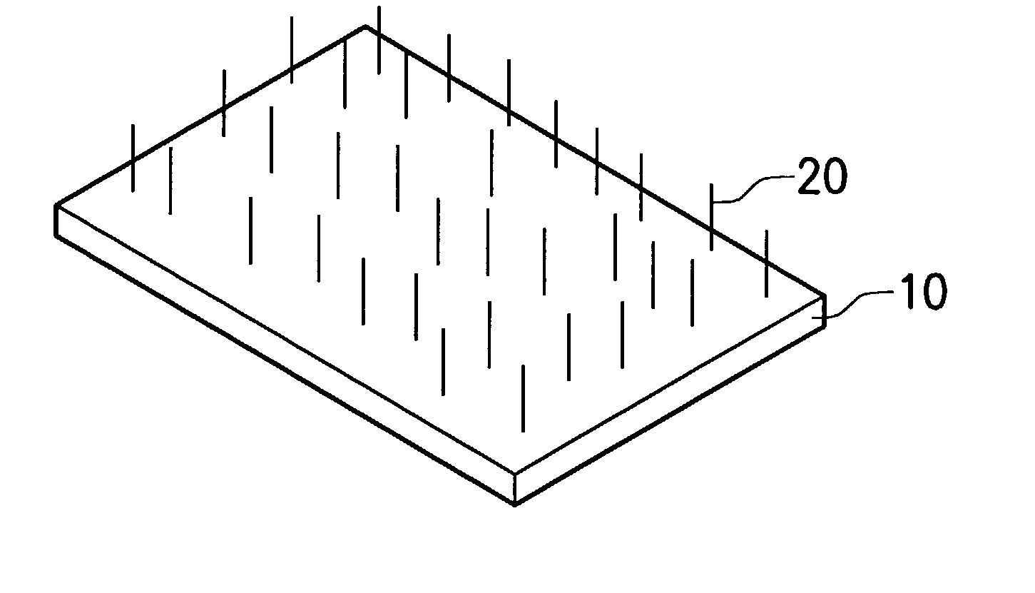
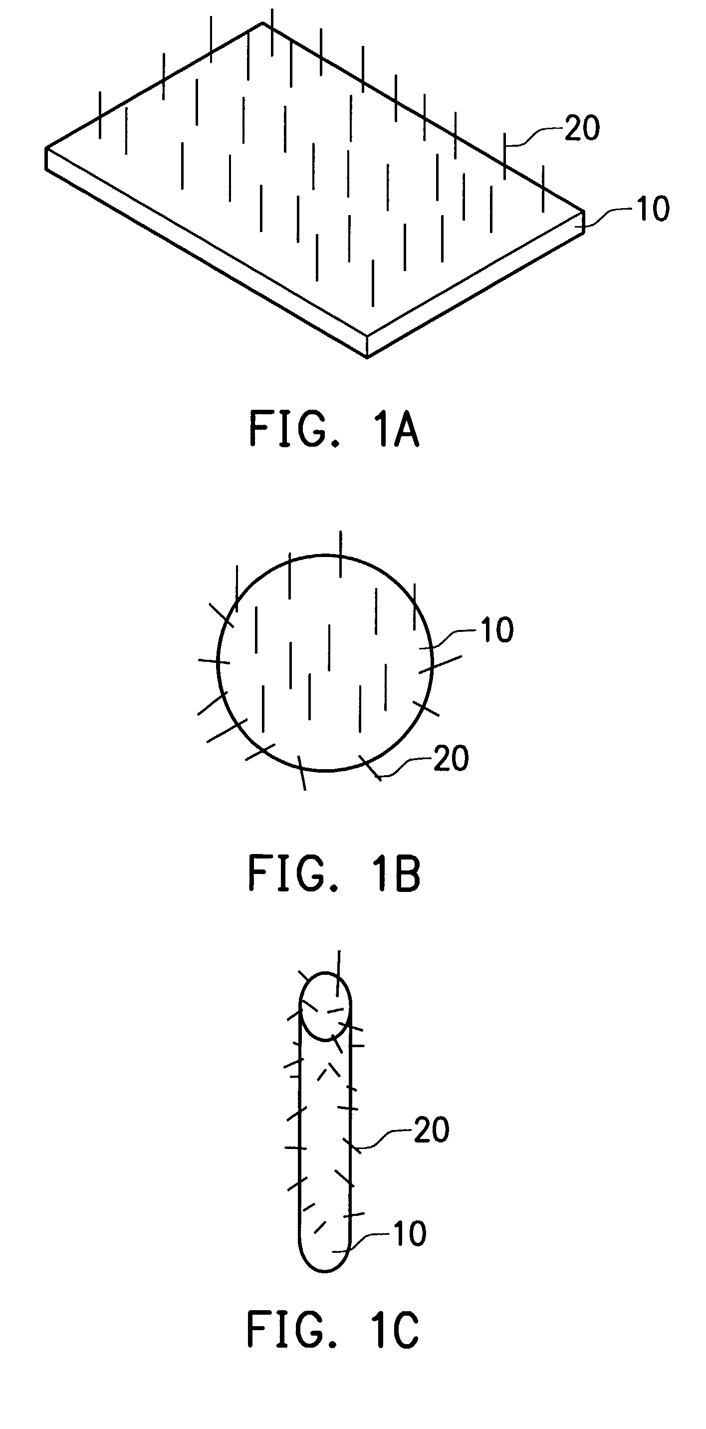
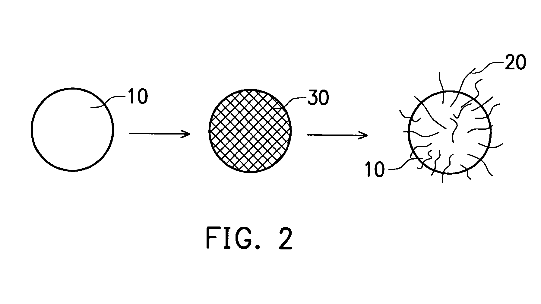
  • Combinative carbon material
  • Combinative carbon material
  • Combinative carbon material

Examples


Embodiment Construction

[0035] 3 g of MCMB was dispersed into 150 ml of water and the solution was stirred for 15 min. 5.5401 g of 28% ammonia was added and the solution was stirred for 5 min. Furthermore, the solution was heated until boiling for 30 min. 3.4 g of 10 wt % nickel nitrate (green in color) aqueous solution was slowly dropped in, and after 5 min, 5.3297 g of 28% ammonia was added. 4 hours of boiling with reflux later, the solution was added with 2.82 g of formaldehyde (reducing agent) and 3.0216 g of 28% ammonia. Finally, the solution was boiled for 30 min, filtered, and dried to obtain the catalyst system (the filtered solution was colorless). 0.2 g of the above treated MCMB (covered with active nanocatalyst) was dispersed into 10 ml of ethanol through ultrasound vibration, and then distributed onto quartz substrate. The substrate was then placed into a CVD reactor and the furnace was heated to 600.degree. C. Inert gas such as Ar (or N.sub.2) was introduced into the reactor in order to remove...


PUM

PropertyMeasurementUnit
Pressureaaaaaaaaaa
Angleaaaaaaaaaa
Temperatureaaaaaaaaaa

Abstract

A combinative carbon material is presented. A large-sized carbon material serving as a support combines with a nano-sized fibrous carbon material, which grows on the support. In addition to the support, a catalyst system includes an active nanocatalyst and an optional co-catalyst. The catalyst system is then reacted with a carbon source at an elevated temperature to form a combinative carbon material.

Description

[0001] 1. Field of the Invention[0002] The present invention relates to a combinative carbon material and its preparation. More particularly, it relates to grafting a nanofibrous carbon material on a larger support of carbon material to form a superior combinative carbon material.[0003] 2. Description of the Related Arts[0004] The nano-fibrous carbon materials with diameters of 1-200 nm include, for example, carbon nanofibers, single-walled carbon nanotubes (SWNTs), multi-walled carbon nanotubes (MWNTs) and others. The preparations of these materials used today are mainly arc discharging, laser vaporization, thermal chemical vapor deposition (hereafter CVD). Among all these, arc discharging (Journet et al., Nature 388:756(1997), and Bethune et al., Nature 363:605(1993)) and laser vaporization (Smally et al., Science 273:483(1996)) have difficulties in controlling length and diameters of products, low production rate, and excess production of amorphous carbon which requires further p...

Claims


Application Information

Patent Timeline
IPC IPC(8): B01J23/755C01B31/02C04B35/52D01F9/127
CPCB82Y30/00B82Y40/00C01B31/0233C01B2202/02C01B2202/06Y10T428/30C04B35/522C04B2235/5248C04B2235/5288C04B2235/94D01F9/127C04B35/52C01B32/162
Inventor HWANG, CHIEN-LIANGTING, JACKCHIANG, JIH-SHUN
Owner IND TECH RES INST
Features
  • Generate Ideas
  • Intellectual Property
  • Life Sciences
  • Materials
  • Tech Scout
  • Unparalleled Data Quality
  • Higher Quality Content
  • 60% Fewer Hallucinations
Learn More