N-type nitride semiconductor laminate and semiconductor device using same
a technology of nitride and semiconductor laminate, which is applied in the direction of semiconductor lasers, coatings, lasers, etc., can solve the problems of difficult to control the crystal growth and difficult to fabricate bulk single crystals, and achieve the effects of less prone to decrease, less forward voltage, and reduced threshold
- Summary
- Abstract
- Description
- Claims
- Application Information
AI Technical Summary
Benefits of technology
Problems solved by technology
Method used
Image

Examples
first embodiment
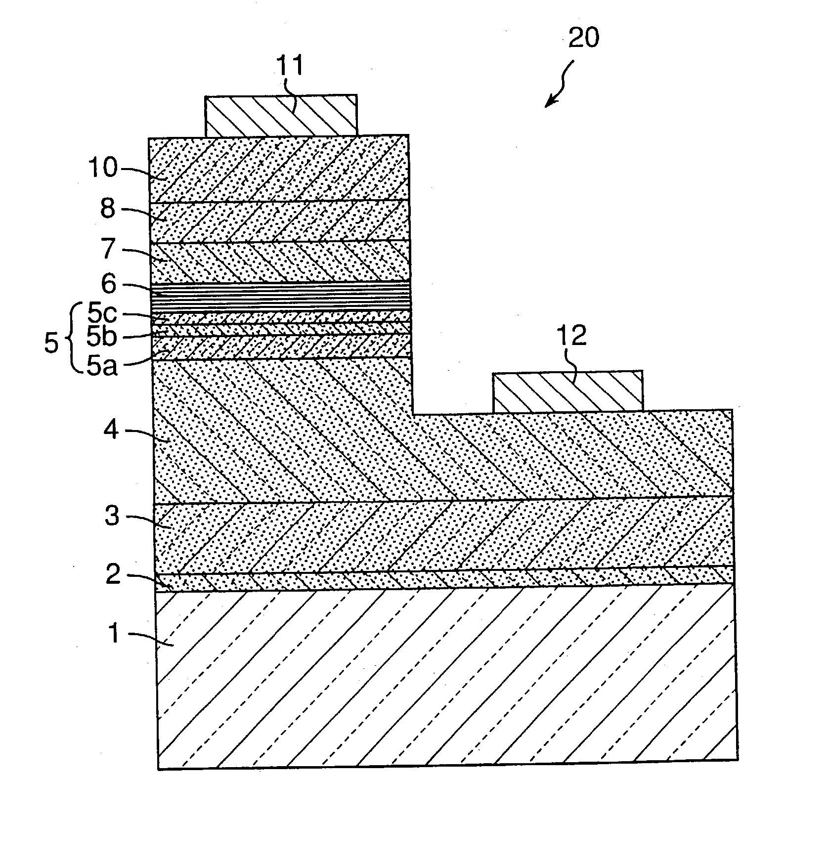
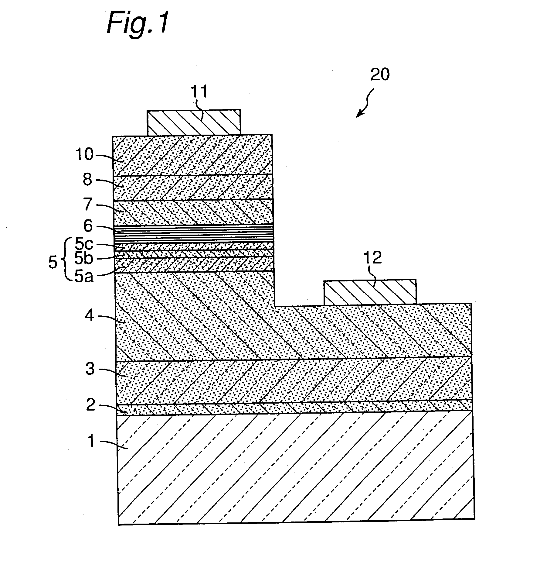
[0043] In the nitride semiconductor device 20, the contact layer 4 including an n-type impurity includes an n-type impurity in a concentration of not less than 1.times.10.sup.17 / cm.sup.3, preferably not less than 3.times.10.sup.18 / cm.sup.3, and more preferably not less than 5.times.10.sup.18 / cm.sup.3. Thus, if the n-type contact layer is doped with an n-type impurity in a large amount in this way, Vf (forward voltage) can be decreased in the case that the nitride semiconductor device 20 is a LED device and the threshold can be decreased in the case that the nitride semiconductor device 20 is a laser device. When the concentration of the impurity departs from the above-mentioned range, Vf is less prone to decrease. In the first embodiment, since the n-type contact layer 4 includes an n-type impurity in a small concentration and is formed on the undoped Al.sub.bGa.sub.1-bN layer 3 having a good crystallinity, even the n-type contact layer 4 including an n-type impurity in a large conc...
second embodiment
[0082] The second embodiment of the invention will be described in the following part. In the second embodiment, the member having the function substantially similar to that in the first embodiment is designated by like reference numeral and a detail-explanation about the member will be omitted.
[0083] Unlike the nitride semiconductor device 20, the nitride semiconductor device 25 of the second embodiment as shown in FIG. 4 comprises another p-type lowly doped layer 9 doper with a p-type impurity in the low concentration between the p-type cladding layer 8 and the p-type contact layer 10. Where the p-type lowly doped layer 9 is formed between the p-type cladding layer 8 and the p-type contact layer 10 as in the nitride semiconductor device 25, a higher static withstand voltage can be achieved. The p-type lowly doped layer 9 will be described in the following part.
[0084] The p-type lowly doped layer 9 which is doped with a p-type impurity in a small concentration and is formed on the ...
example 1
[0088] Table 2 shows a laminated structure of the LED device of Example 1.
2 TABLE 2 layer composition Buffer layer 2 Al.sub.0.25Ga.sub.0.75N, thickness: 100 .ANG. Undoped GaN layer 3 GaN, thickness: 1.5 .mu.m n-type contact layer 4 Si doped GaN, thickness: 2.25 .mu.m n-side first multi-GaN, thickness: 3000 .ANG. / Si doped layered film 5 GaN, thickness: 300 .ANG. / GaN, thickness: 50 .ANG. Total thickness: 3350 .ANG. n-side second multi- (GaN, thickness: 40 .ANG. / In.sub.0.13Ga.sub.0.87N; layered film 6 thickness: 20 .ANG.) .times. 10 + GaN, thickness: 40 .ANG. Total thickness: 640 .ANG. Active layer 7 (GaN, thickness: 200 .ANG. / In.sub.0.4Ga.sub.0.6N, thickness: 30 .ANG.) .times. 4 + GaN, thickness: 200 .ANG. Total thickness: 1120 .ANG. p-type multi-layered (Mg doped Al.sub.0.2Ga.sub.0.8N, thickness: 40 cladding layer 8 .ANG. / Mg doped In.sub.0.03Ga.sub.0.97N, thickness: 25 .ANG.) .times. 5 + Mg doped Al.sub.0.2Ga.sub.0.8N, thickness: 40 .ANG. Total thickness: 365 .ANG. p-type GaN contact...
PUM
| Property | Measurement | Unit |
|---|---|---|
| thickness | aaaaa | aaaaa |
| voltage | aaaaa | aaaaa |
| thickness | aaaaa | aaaaa |
Abstract
Description
Claims
Application Information
 - Generate Ideas
- Intellectual Property
- Life Sciences
- Materials
- Tech Scout
- Unparalleled Data Quality
- Higher Quality Content
- 60% Fewer Hallucinations
Browse by: Latest US Patents, China's latest patents, Technical Efficacy Thesaurus, Application Domain, Technology Topic, Popular Technical Reports.
© 2025 PatSnap. All rights reserved.Legal|Privacy policy|Modern Slavery Act Transparency Statement|Sitemap|About US| Contact US: help@patsnap.com