Method for production of silica optical fiber preforms

a technology of silica and optical fiber, applied in glass making apparatus, manufacturing tools, instruments, etc., can solve the problems of difficult fabrication of cores or claddings with steep doping profiles, methods that require a step, and ultraviolet radiation-induced color centers, etc., to achieve the effect of efficient production of optical

Inactive Publication Date: 2004-02-19
BIOLITEC UNTERNEHMENSBETEILLIGUNGS II AG
View PDF4 Cites 21 Cited by
  • Summary
  • Abstract
  • Description
  • Claims
  • Application Information

AI Technical Summary

Benefits of technology

0012] It is an object of the present invention to provide a method and d...

Problems solved by technology

In UV fibers, however, the presence of Germanium can result in ultraviolet radiation-induced color centers, which are point defects in the core's silica that generate absorption bands in the UV and visible spectrum that deteriorate the optical fiber transmission in that spectral region.
The main disadvantage of MCVD, OVD, and VAD technologies for manufacturing preforms with active cores is that these methods require a step during the deposition in which soot glass layers are formed.
The presence of soot makes it difficult to fabricate cores or claddings with steep doping profiles.
Another disadvantage of these methods is the difficulty of achieving homogeneous doping, especially for lightguides with high rare earth element (REE) concentrations.
Additionally, only low pressure microwave plasma techniques have been able to provide effective N.sub.2-dissociation (when the electron temperature is essentially higher than gaseous one, or when T.sub.e>>T.sub.g) because of the high bond energy of N.sub.2.
Despite the advantages of plasma-chemical technologies in optical fiber preform production, effective tubeless microwave plasma-chemical technologies for the production of optical fiber preforms, including for example, activated and N.sub.2-doped preforms, have not been developed before the present time.
However, this method possesses three major drawbacks.
The first major disadvantage of the Beerwald patent is its inability to produce uniform microwave power density both in the microwave discharge and on the rod face using only either an E.sub.01 excitation mode or a ci...

Method used


Image

  • Method for production of silica optical fiber preforms
  • Method for production of silica optical fiber preforms
  • Method for production of silica optical fiber preforms

Examples


example 2

[0062] Production of a Preform with Cladding and Al and Er Doped Core

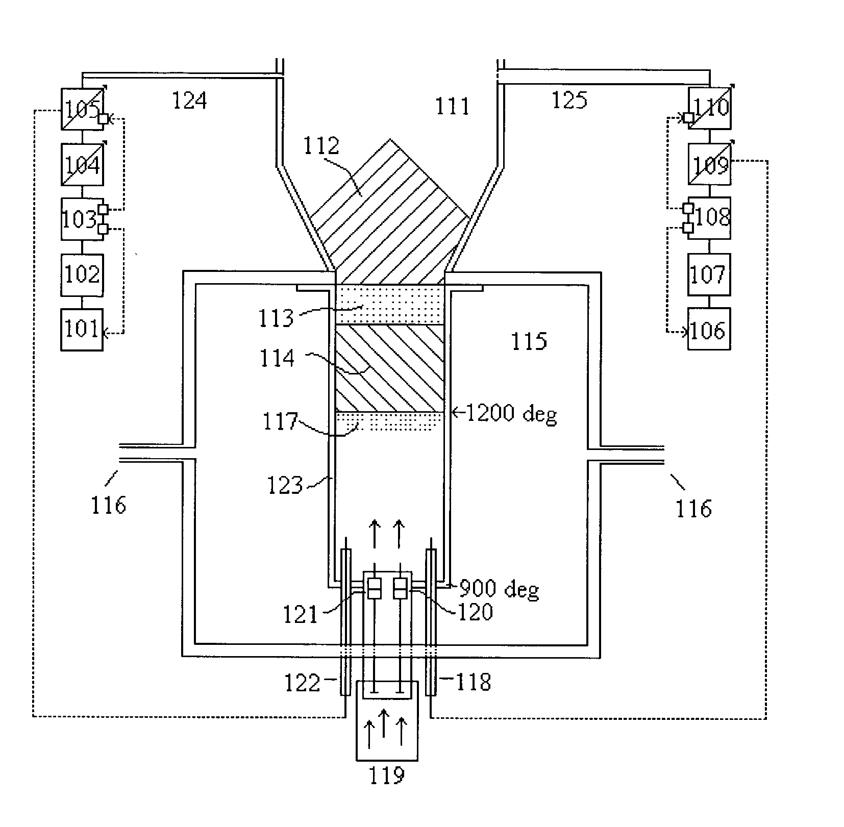
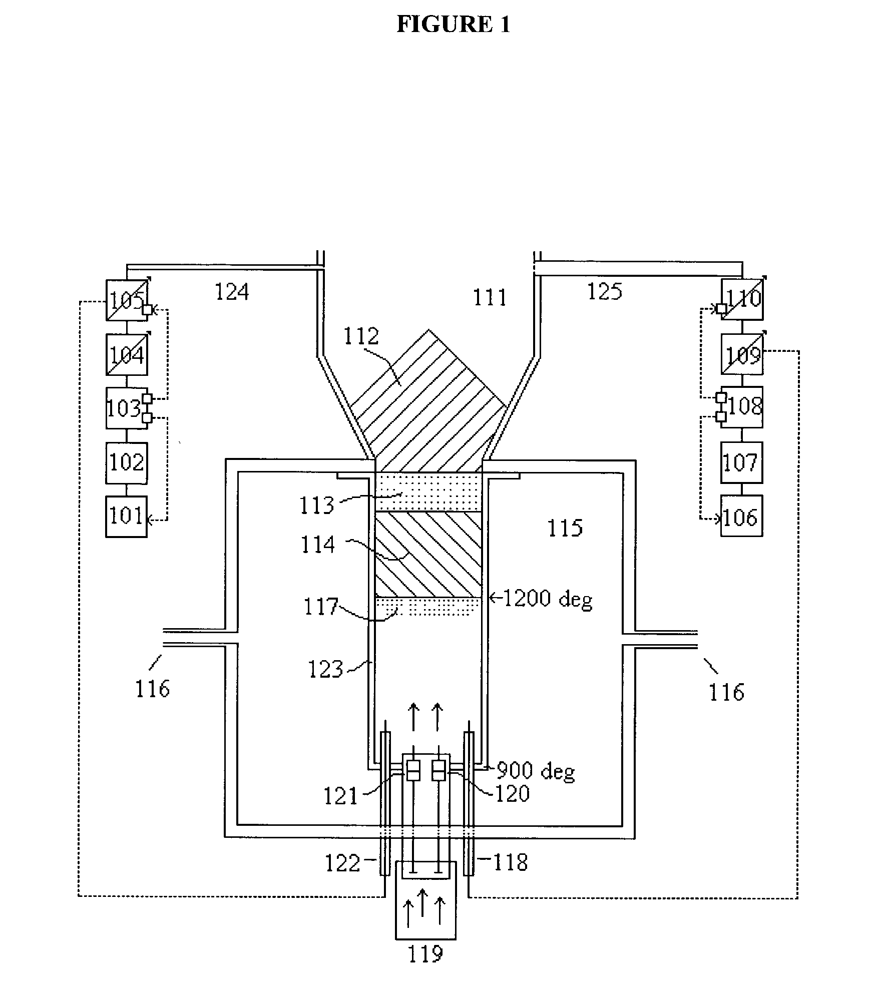
[0063] With the present invention, a preform can be manufactured that features a core whose refractive index is radially variable. The produced reflective cladding consists of fluorine-doped silica and the core consists of silica doped with aluminum and erbium. A gas mixture consisting of O.sub.2+SiCl.sub.4+C.sub.3F.sub.8+ErCl.sub.3(waterless vapor)+AlCl.sub.3(waterless vapor) is supplied to the microwave plasma zone via gas supply system 119. AlCl.sub.3 and ErCl.sub.3 vapors are supplied to the plasma from the closed silica containers 120 and 121, (with ErCl.sub.3 and AlCl.sub.3 powders) which are located under the microwave plasma at the 900.degree. C. temperature zone in the graphite tube 123. Condensation of ErCl.sub.3 and AlCl.sub.3 in the reaction zone during vapor transportation is avoided because the temperature increases around the supplying vapors in the plasma zone. The activator flow is determined by pr...

example 3

[0069] Preform Manufacture without Pulsed Generator 106

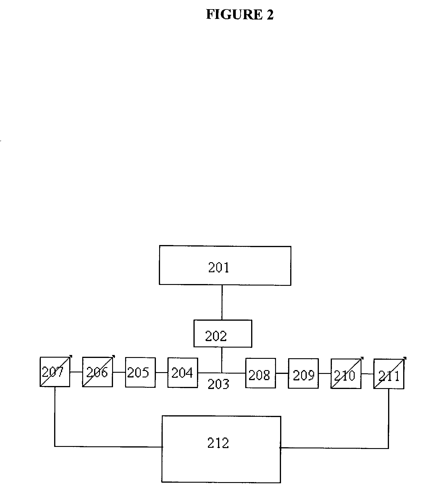
[0070] This alternative embodiment of the present invention presents a simpler device scheme for manufacturing activated optical fiber preforms, SiON core preforms, SiO.sub.2 rods doped by nitrogen and SiO.sub.2 rods doped by Al (Ge) and different types of REE (Er and so on). In this case the microwave power density on the rod face and in the microwave plasma will be lower (150-160 W / cm.sup.2) then in those embodiments that include a pulsed microwave generator. The deposition rate is approximately 1-1.5 g / min in this case. A diagram of this installation is shown in FIG. 2.

[0071] Continuous microwave generator 201 emits radiation at preferably 2450 MHz and 6 kW through ferrite circulator 202, which "protects" generator 201 from reflected microwave power, to power divider 203 which divides this power into two equal parts for 2 microwave energy channels which are divided by the ferrite circulators 204 and 208. The excitation proces...

example 4

[0074] The Method for Production of an SiON Rod for Use in Subsequent Manufacture of an Optical Fiber Preform

3 Microwave power (impulse), E.sub.01 wave, kW 7.5 Impulse duration, ms 1.0 Impulse repetition rates, Hz 100 Microwave power (continuous), H.sub.11 wave 0-4.5 with rotating polarization, kW Gas pressure, torr 15 Mutual gas flow, cm.sup.3 / min 12000 N.sub.2 flow, cm.sup.3 / min 6500 O.sub.2 flow, cm.sup.3 / min 1500 SiCl.sub.4 flow, cm.sup.3 / min 3800 Ar flow, cm.sup.3 / min 200 Silica rod diameter, mm 60 Rod face temperature, C. 1200 Rate of rod rotation, rev / min 100

[0075] The deposition rate of SiON glass is 3 g / min. SiON rod (60 mm diameter, 210 mm length, more than 2 kg weight) is fabricated for 12 hours of continuous deposition process.


PUM

PropertyMeasurementUnit
Volumeaaaaaaaaaa
Timeaaaaaaaaaa
Mass flow rateaaaaaaaaaa

Abstract

A device and method is disclosed for manufacturing optical fiber preforms utilizing microwave plasma assisted chemical vapor deposition. Precursor gas is introduced to the face of a vertically mounted dielectric rod, and a plasma is struck by means of simultaneous excitation of an E01 type wave and an H type wave with rotating linear polarization. The silica rod is positioned so that its face is at the bottom of the tube. Precursor gas is delivered from a position below the face of the silica rod, and microwave energy, which travels through the rod to the rod face, is delivered from a source positioned above the rod. With this configuration, a uniformly dense plasma localized on the face of the rod can simultaneously deposit both a pure or doped core and a doped cladding. It is also useful for creating waveguides, preform cores for use as substrates in creating optical fiber preforms, capillaries and ceramic rods.

Description

[0001] 1. Field of the Invention[0002] The invention relates to the manufacture of optical fiber preforms and preform rods.[0003] 2. Information Disclosure Statement[0004] Silica activated lightguides with flourine doped silica (SiO.sub.2--F) claddings and cores doped with Al or Ge and / or Rare earth elements (Neodymium, Erbium, Holmium, Ytterbium, Europium and so on) are widely used for the creation of optical fiber amplifiers, lasers and sensors of different types. In UV fibers, however, the presence of Germanium can result in ultraviolet radiation-induced color centers, which are point defects in the core's silica that generate absorption bands in the UV and visible spectrum that deteriorate the optical fiber transmission in that spectral region. Lightguides containing an SiON core and SiO.sub.2--F cladding would be useful for ultraviolet applications because of the absence of Germanium in the lightguide core. SiON cores are useful in that they provide the ability to easily change...

Claims


Application Information

Patent Timeline
IPC IPC(8): C03B37/014C03C3/04C03C13/04H05H1/24
CPCC03B37/01426C03B2201/24H05H1/24C03C13/046C03C3/045H05H1/46H05H1/4622
Inventor BLINOV, LEONID M.
Owner BIOLITEC UNTERNEHMENSBETEILLIGUNGS II AG
Why Eureka
Try Eureka