Process for the production of elemental material and alloys

a technology of elemental materials and alloys, applied in the field of process for the production of elemental materials, can solve the problems of uncontrollable and sporadic reaction, increased product cost by a factor of two to three, laborious, etc., and achieves the effects of reducing material or agent, reducing energy consumption, and less expensiv

Inactive Publication Date: 2004-07-01
MILLENNIUM INORGANIC CHEM
View PDF23 Cites 68 Cited by
  • Summary
  • Abstract
  • Description
  • Claims
  • Application Information

AI Technical Summary

Benefits of technology

0037] Another advantage of the present invention is that the reducing material or agent is in solid form. The use of a solid reducing agent provides many advantages which were heretofore overlooked. For example, the use of a reducing agent that is in solid form enables the effective use of a fluidized bed reactor, which is highly desirable due to the control over the process conditions that is afforded by this type of reactor. In addition, at the lower reaction temperatures that are used with a reducing agent in solid form, the elemental material (or alloy) is formed as a dry powder with less impurities (e.g., foreign material trapped in the elemental material as inclusions or stuck to the surface of the elemental material) than the elemental material that is formed by processes wherein the elemental material is partly or completely molten during the reaction process.
0038] The lower reaction temperature also results in lower energy consumption, the ability to use reactors made of less expensive materials that would not withstand the higher reaction temperatures of the prior art processes, and less reactor maintenance, all of which will result in a lower final product cost.
0039] Another advantage of the reducing agent being in solid state form is that it allows the whole process to be a closed system which makes a continuous process possible and eliminates the introduction of impurities during processing.
0040] The fluidized bed that is used in the process of the present invention can be a bubbling fluidized bed, an entrained flow reactor, a circulating fluidized bed, a fast fluidized bed or any other similar type of reactor which is suitable for gas-solid reactions with excellent mass and heat transfer. Although the fluidized beds discussed above consist essentially of the reducing agent, it is also possible and in some cases desirable to use a fluidized bed material that comprises an inert media in combination with the reducing agent. The desirability of the use of an inert media in the fluidized bed material will depend on such factors as the particular feed material, reducing agent, production equipment and production conditions that are to be used. It is believed that such a modification to the fluidized bed composition is within the skill of the art and does not require further description or teachings herein to be successfully practiced.
0041] Depending on the reaction conditions to be used and the composition of the reactor walls, it may be desirable to coat the interior surface(s) of the fluidized bed reactor with a protective layer to minimize contamination of the elemental material with impurities that are leached or otherwise removed from the reactor walls. For example, when the elemental material to be produced is titanium, the protective layer could be formed from titanium, a substance that will not alloy with titanium or a substance that is non-reactive with (or inert to) titanium.
0042] The following Examples embody the invention, but should not be used to limit the scope of the invention in any way.

Problems solved by technology

For both processes, the reaction is uncontrolled and sporadic and promotes the growth of dendritic titanium metal.
The processing of the titanium sponge into a usable form is difficult, labor intensive, and increases the product cost by a factor of two to three.
The processes discussed above have several intrinsic problems that contribute heavily to the high cost of titanium production.
Both processes are batch processes and batch process production is inherently capital and labor intensive.
The processes also suffer from low productivity because the reactor has to be charged, heated, and discharged, which involves a long down time between batches.
Furthermore, due to the batch nature of these processes, there is significant quality variation in the titanium metal produced from batch to batch.
Additionally, the titanium sponge produced by these processes requires further substantial processing to produce titanium in a usable form; thereby increasing cost, increasing hazard to workers and exacerbating batch quality control difficulties.
In addition, both processes are energy intensive and neither process utilizes the large exothermic energy reaction, requiring substantial energy input for titanium production (approximately 6 kW-hr / kg product metal).
The titanium tetrachloride used in the commercial production of titanium metal is usually obtained by chlorinating relatively high-grade titanium dioxide ore, which also partially contributes to the high cost of the metal.
However, also as discussed above, the current commercial methods use batch processing, which is undesirable.

Method used


Image

  • Process for the production of elemental material and alloys
  • Process for the production of elemental material and alloys
  • Process for the production of elemental material and alloys

Examples


example 1

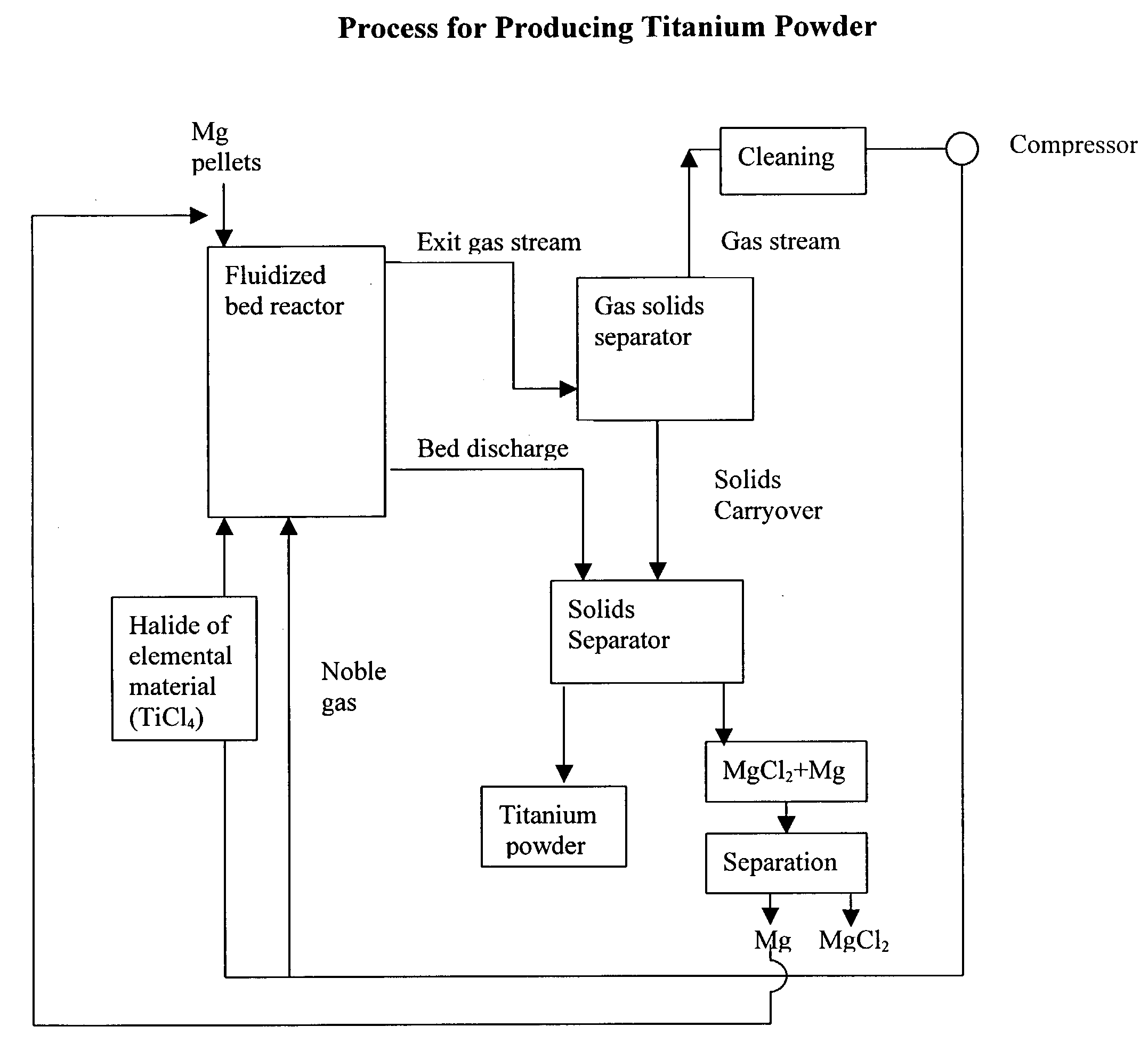
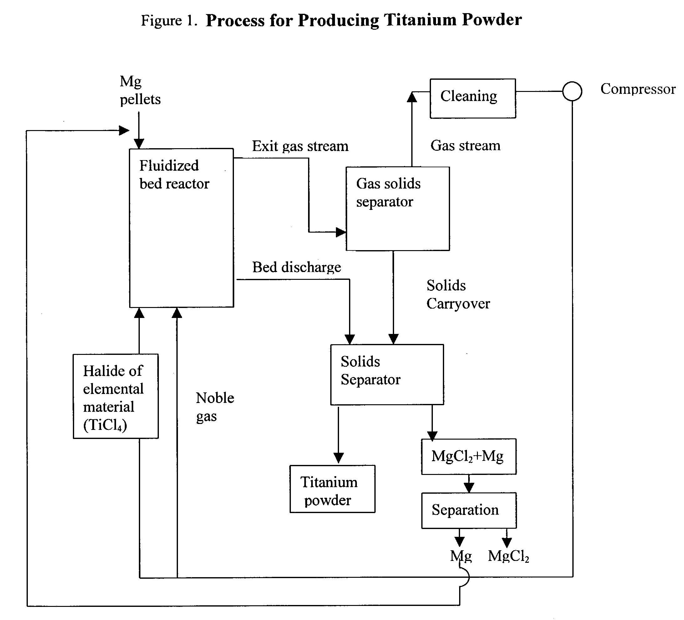
[0043] 150 grams of magnesium granules (-20+100 mesh, Stock#00869, obtained from Alfa Aesar) were placed in a custom-made quartz fluidized bed reactor (55 mm ID, length=about 3 feet). A quartz fritted disc (55 mm diameter, made by Heraeus-Amersil) was used as the bed support. Argon was introduced at the bottom of the reactor as the fluidizing gas. The reactor was heated to 450.degree. C. in a furnace while the bed was fluidizing. The superficial gas velocity of argon was 0.8 ft / sec and the flowrate was 14.4 liters / min. When the bed temperature reached 450.degree. C., TiCl.sub.4 vapor was introduced into the fluidized bed reactor to begin the reduction reaction. The TiCl.sub.4 vapor was introduced into the fluidized bed reactor by passing some of the argon through a heated container holding TiCl.sub.4 vapor and then feeding the exhaust stream from that container (i.e., argon and TiCl.sub.4 vapor) into the bottom of the reactor. The bed temperature was gradually increased to 620.degre...

example 2

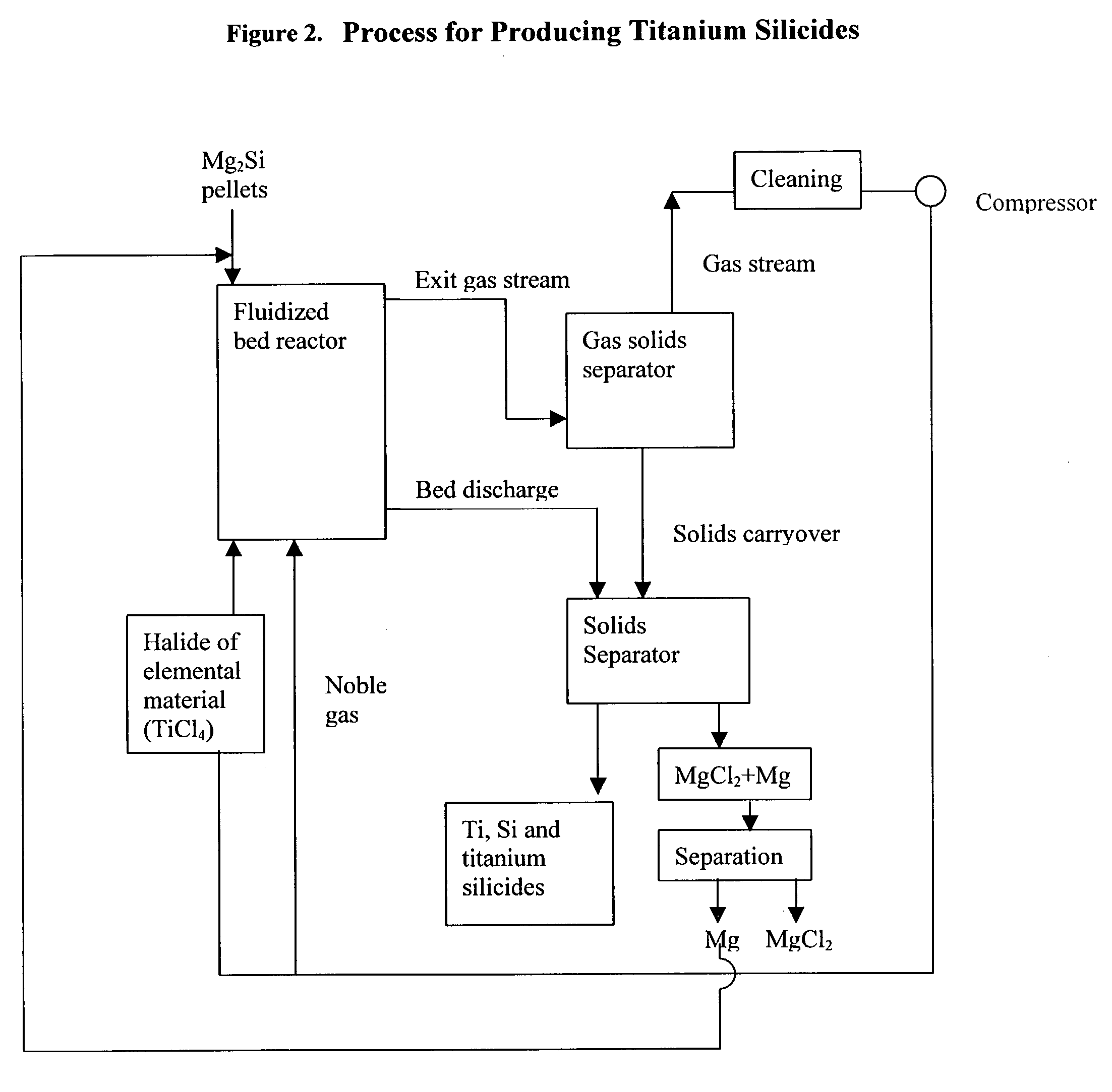
[0052] 448 grams of a previously used bed which initially consisted of silicon (+140 mesh, a sample from Union Carbide), and, at the time of this experiment comprised 24% magnesium silicides and 76% of silicon, were placed in a custom-made quartz fluidized bed reactor (55 mm ID, length=about 3 feet). A quartz fritted disc (55 mm diameter, Heraeus-Amersil) was used as the bed support. The reactor was coated with TiN inside (by spray painting with a TiN paint) to prevent reaction between reductant metal and the quartz reactor. Argon was introduced at the bottom of the reactor as the fluidizing gas. The reactor was heated to 550.degree. C. in a furnace while the bed was fluidizing. The superficial gas velocity of argon was 0.34 ft / s and the flowrate was 5.2 liters / min. When the bed temperature reached 550.degree. C., TiCl.sub.4 vapor was introduced into the fluidized bed reactor to begin the reduction reaction. After TiCl.sub.4 was introduced for 29 minutes, 124 grams of magnesium meta...


PUM

PropertyMeasurementUnit
sizeaaaaaaaaaa
temperaturesaaaaaaaaaa

Abstract

The present invention relates to a process for the production of an elemental material, comprising the step of reacting a halide of the elemental material with a reducing agent in solid form in a fluidized bed reactor at a reaction temperature which is below the melting temperature of the reducing agent. In a preferred embodiment of the present invention, the elemental material is titanium and the titanium is produced in powder form. The invention also relates to the production of alloys or intermetallics of the elemental materials.

Description

[0001] (1) Field of the Invention[0002] The present invention relates to a process for the production of an elemental material, comprising the step of reacting a halide of the elemental material with a reducing material in solid form in a fluidized bed reactor at a reaction temperature which is below the melting temperature of the reducing material. In a preferred embodiment of the present invention, the elemental material is titanium and the titanium is produced in powder form. The invention also relates to the production of alloys and intermetallic compounds of the elemental materials.[0003] (2) Description of Related Art[0004] The Kroll process and the Hunter process are the two present day methods of producing titanium commercially. In the Kroll process, titanium tetrachloride is chemically reduced by magnesium at temperatures between 800 and 900.degree. C. The process is conducted in a batch fashion in a metal (steel) retort with an inert atmosphere (usually helium or argon). M...

Claims


Application Information

Patent Timeline
Patent Type & Authority Applications(United States)
IPC IPC(8): B22F9/20C22B5/14C22B34/12
CPCB22F9/20C22B34/1272C22B5/14
Inventor ZHOU, LINGSCHNEIDER, FREDERICK E. L. JR.DANIELS, ROBERT J.MESSER, THOMASPEELING, JON PHILIP R.
Owner MILLENNIUM INORGANIC CHEM
Why Eureka
Try Eureka