Manufacturing apparatus and method for carbon nanotube

a technology of carbon nanotubes and manufacturing apparatuses, which is applied in the direction of carbonsing rags, chemical/physical/physical-chemical processes, energy-based chemical/physical/physical-chemical processes, etc., can solve the problems of difficult to obtain a few grams of specimens, no particular boundary, and the controversy of carbon nanotube generation methods

Inactive Publication Date: 2004-09-02
FUJIFILM BUSINESS INNOVATION CORP
View PDF3 Cites 30 Cited by
  • Summary
  • Abstract
  • Description
  • Claims
  • Application Information

AI Technical Summary

Problems solved by technology

However, there is no particularly definite boundary therebetween.
However, a mechanism of generating carbon nanotubes with those methods is controversial in various respects, and a detailed growth mechanism is not disclosed even now.
However, with this method, it is extremely difficult to obtain a few grams of specimen, so that the method is hardly used now.
Incidentally, the carbon nanotubes synthesized using those synthesis methods are more expensive than other materials.
In particular, under the current circumstances, the arc discharge which is a method capable of manufacturing a carbon nanotube that has high crystallinity with few defects is higher in the manufacturing cost than that of the chemical vapor deposition.
However, the graphite rod is expensive, leading to great increase in the manufacturing cost for the carbon nanotube.
Accordingly, the cost of the carbon nanotube itself is increased.
However, the above-mentioned criterion does not apply to a hardness in the case of using compressed powder such as activated carbon.
If the burning temperature is too low, the porous carbonaceous material may not ensure a sufficient electrical conductivity.
However, when an angle between the directions is excessively large, the electrodes may be broken due to the relationship among the magnetic field, the electric field, and the force.

Method used


Image

  • Manufacturing apparatus and method for carbon nanotube
  • Manufacturing apparatus and method for carbon nanotube
  • Manufacturing apparatus and method for carbon nanotube

Examples


Embodiment Construction

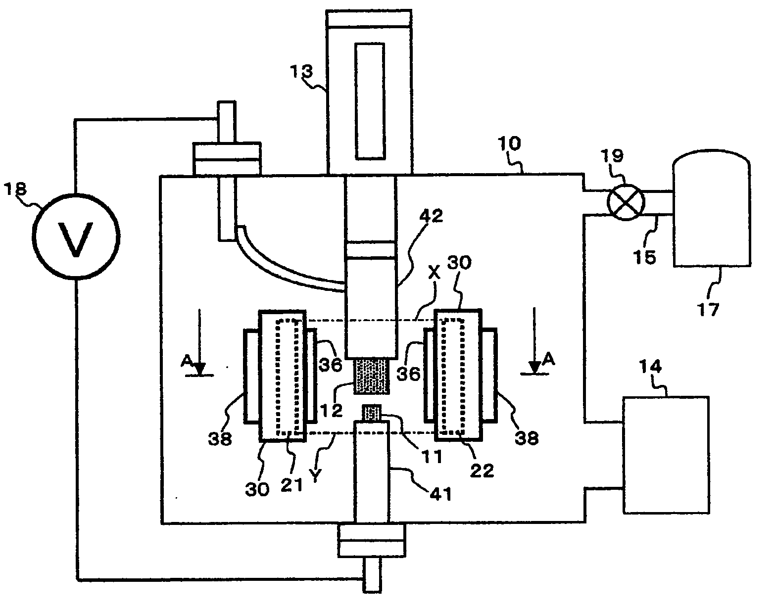
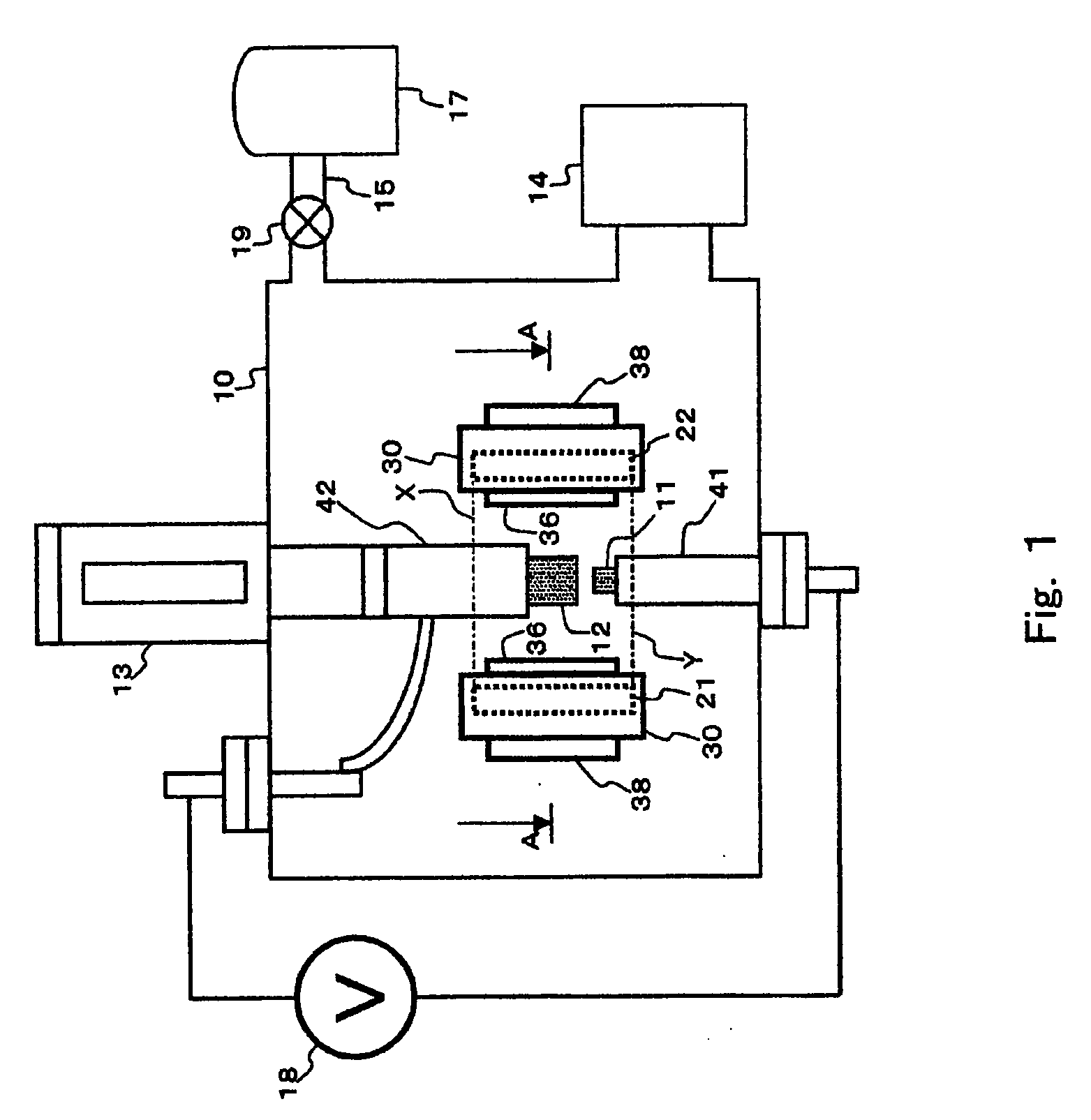
[0115] Hereinafter, description will be made of an example of the present invention. However, the present invention is not limited to the example. The manufacturing apparatus shown in FIG. 1 is used to manufacture a carbon nanotube. At this time, binchotan charcoal serving as the porous carbonaceous material is used as the electrode 12 (anode). The binchotan charcoal to be used is subjected to the dehydration process by the heat dehydration method at 200.degree. C. in the atmosphere for two hours. FIG. 6 is a scanning electron microscope (SEM) photograph (at a magnifying power of 500) of a surface of the binchotan charcoal used in this example. It is observed from the photograph that there exist a number of holes on the surface of the binchotan charcoal.

[0116] Note that for the observation using the scanning electron microscope, a scanning electron microscope S-4500 manufactured by Hitachi Ltd., was used. Also, the magnifying power for the photograph has an error to a certain degree...


PUM

PropertyMeasurementUnit
diameteraaaaaaaaaa
Young's modulusaaaaaaaaaa
temperatureaaaaaaaaaa

Abstract

Provided is a manufacturing apparatus for a carbon nanotube, including: at least two electrodes whose tips are opposed to each other, and a power supply that applies a voltage between the two electrodes to generate discharge plasma in a discharge area between the two electrodes. By using a porous carbonaceous material for at least one of the two electrodes, it is possible to provide a manufacturing apparatus and method for a carbon nanotube, which are capable of manufacturing at a low cost the carbon nanotube that is inexpensive and has a further higher purity.

Description

FIELD OF THE INVENTION AND RELATED ART STATEMENT[0001] The present invention relates to a manufacturing apparatus and method for a carbon nanotube whose industrial availability has been attracting attention in recent years.[0002] The carbon nanotube has an extremely finer diameter than that of a general carbon fiber, a high Young's modulus, and a high electrical conductivity, thereby attracting attention as a new industrial material.[0003] A material having a diameter of 1 .mu.m or smaller which is finer than the carbon fiber is generally called a carbon nanotube and distinguished from the carbon fiber. However, there is no particularly definite boundary therebetween. By a narrow definition, the material whose hexagonal mesh carbon surface is substantially parallel to an axis is called a carbon nanotube, and even a variant of the carbon nanotube, around which amorphous carbon exists, is included in the carbon nanotube (Note that the narrow definition is applied to the carbon nanotub...

Claims


Application Information

Patent Timeline
Patent Type & Authority Applications(United States)
IPC IPC(8): B01J19/08C01B31/02
CPCB01J19/087B01J19/088B01J2219/0809B01J2219/0828C01B31/0226B01J2219/0894B82Y30/00B82Y40/00B01J2219/0886C01B32/16
Inventor ANAZAWA, KAZUNORIKISHI, KENTAROHIRAKATA, MASAKIWATANABE, HIROYUKISHIMIZU, MASAAKI
Owner FUJIFILM BUSINESS INNOVATION CORP
Why Eureka
Try Eureka