Apparatus and method for in-situ chamber cleaning in a compound semiconductor etching system

Inactive Publication Date: 2005-01-13
ZAJAC JOHN +1
View PDF7 Cites 4 Cited by
  • Summary
  • Abstract
  • Description
  • Claims
  • Application Information

AI Technical Summary

Benefits of technology

[0004] The invention uses an automatic method of wet cleaning both the process chamber and the closely positioned cold trap with its associated plumbing.

Problems solved by technology

The etching of many arsenic containing III-V compound semiconductors, including Gallium Arsenide, produces toxic reaction products such as Arsenic Chloride.
This condensate material and materials formed by reaction of condensates with atmospheric gases or moisture are hazardous to the health of the worker who does periodic cleaning or maintenance of the reactor.
While in-situ gas phase cleaning does not expose workers to the chamber interior, manual cleaning does expose workers.
Normally, gas-phase in-situ chamber cleans, which can be very slow and time consuming, still leave hazardous amounts of toxic arsenic compounds condensed in the process chamber and pumping system.
Due to this, manual cleaning of the chamber and pumping system for III-V etching systems is done at substantial expense (and some risk) by personnel using hazardous material apparatus.
In this case there will be a great deal more toxic material deposited on the chamber walls than during conventional etching.
In addition, there will tend to be large amounts of condensed toxic compounds in vacuum system components such as throttle valves and isolation valves.
This will necessitate much more frequent manual cleaning of the chamber and pumping system than is currently performed on such etching chambers—with a substantial increase in operating cost per wafer etched.
One alternative, sometimes used in

Method used


Image

  • Apparatus and method for in-situ chamber cleaning in a compound semiconductor etching system
  • Apparatus and method for in-situ chamber cleaning in a compound semiconductor etching system
  • Apparatus and method for in-situ chamber cleaning in a compound semiconductor etching system

Examples


Embodiment Construction

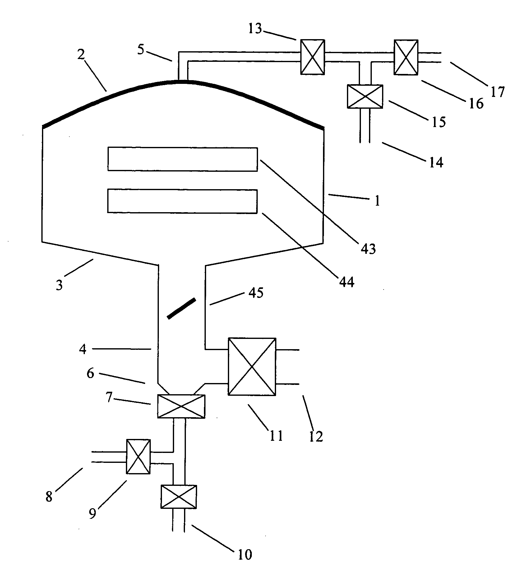
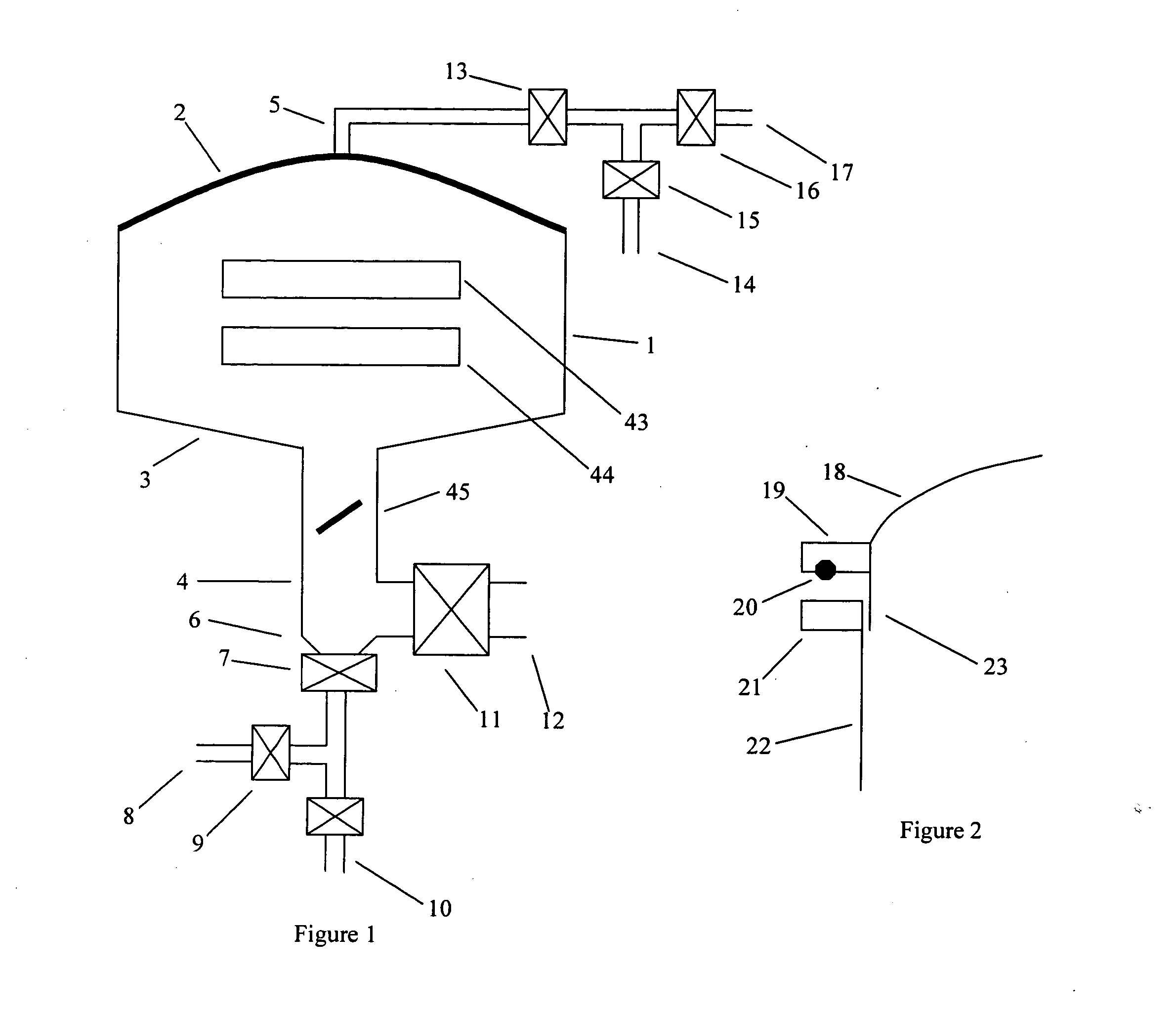
[0012] The following description can be applied to any etching system but is most frequently used with a narrow gap parallel plate reactor where the top electrode also serves as the gas supplying showerhead.

[0013]FIG. 1 shows a process chamber 1 with lid 2. The lid is curved to allow water flow to provide washing of the lid itself, the chamber walls, the chamber bottom 3 and the lower plumbing lines. Splashing and spraying would allow for the cleaning of electrodes within the reactor (FIG. 1, items 43 and 44). Exhaust line 4 contains a butterfly throttle valve 45, for controlling chamber pressure connects to the main vacuum valve 11. Exhaust line 4 has a sloped bottom 6 to reduce the trapping or puddling of any cleaning liquid. Valve 7 is a vacuum isolation valve used to drain liquid from the chamber and vacuum line 4. Drain line 8 provides means of drainage during cleaning. Valve 9 provides a means of isolating the vacuum system from the backpressure of the drain. Valve 10 is clos...


PUM

PropertyMeasurementUnit
Solubility (mass)aaaaaaaaaa
Stabilityaaaaaaaaaa
Safety-related propertiesaaaaaaaaaa

Abstract

This invention consists of an apparatus and method of permitting automatic, in-situ cleaning of the process chamber and condensation trap of the vacuum pumping system used for etching Gallium Arsenide and other materials producing toxic and condensable etching by-products. This automated cleaning greatly reduces the danger of human exposure to the toxic materials and by-products of the etching. There are two key features. First, the process chamber and condensation trap are designed so that all components are vacuum-sealed to each other (or may be purged with inert gas) such that during wafer processing gas phase species from the process environment cannot condense in narrow spaces between components in the chamber. The surfaces of all parts that come in contact with, and may react to, enchant byproducts, process gases, or any cleaning liquid, are covered with nickel, or Teflon or other highly chemically inert coating. The second feature is that a liquid cleaning cold wall condensation trap is used to capture etching byproducts. The reactor and trap are cleaned separately or simultaneously by injecting water, with or without, liquid cleaner(s) into the process chamber through a set of injection holes. Said liquid cleaner may contain acidic, caustic or other reagents. The wet cleaning step dissolves or converts to soluble form any arsenic (or other toxic) compounds condensed in the process chamber or trap. In addition the flushing action of the liquids aids in the dislodging and removal of any insoluble or low soluble deposits. Liquid cleaning is typically followed with a heated air or nitrogen flow to evaporate any remaining liquid. Said cleaning process may have multiple steps. In a typical clean sequence the chamber and trap are flushed with water-based cleaning compounds that may be acidic or basic. This may be followed by a water-based rinse to rinse away all condensates or remnant compounds from the etching process. The next step may be a rinse with an alcohol or non-aqueous liquid with higher vapor pressure to scavenge or drive out remaining water. And finally, the system may be purged with a drying gas such as nitrogen to remove remnant traces of liquid. The result of such flushing is the virtually complete removal of traces of arsenic and its compounds from the system so as to greatly improve the safety of any ensuing manual chamber clean or replacement of parts. This cleaning process also maintains a more consistent process environment for process stability and reduces particulate that can affect yield.

Description

RELATED APPLICATION [0001] This application is based upon Provisional Application No. 60 / 472,279, filed May 20, 2003, the priority of which is claimed.BACKGROUND OF THE INVENTION [0002] The etching of many arsenic containing III-V compound semiconductors, including Gallium Arsenide, produces toxic reaction products such as Arsenic Chloride. These etch reaction products have modest vapor pressures at room temperature and may condense on the walls of the etching reactor and in the vacuum pumping system used to exhaust the etching chamber. This condensate material and materials formed by reaction of condensates with atmospheric gases or moisture are hazardous to the health of the worker who does periodic cleaning or maintenance of the reactor. Previous methods of cleaning reactors used for gallium arsenide etching used gas phase cleaning followed by manual cleaning. While in-situ gas phase cleaning does not expose workers to the chamber interior, manual cleaning does expose workers. Ma...

Claims


Application Information

Patent Timeline
IPC IPC(8): B08B9/08H01L21/3065
CPCH01L21/3065B08B9/08
Inventor ZAJAC, JOHNSAVAS, STEPHEN EDWARD
Owner ZAJAC JOHN
Why Eureka
Try Eureka