Methods, systems and devices for improving ventilation in a lung area

a technology for lung area and ventilation, applied in the direction of valves, mechanical devices, operating means/releasing devices, etc., can solve the problems of reducing the surface area for gas transfer, reducing bulk air flow exchange, and sub>2 /sub>retention of trapped air, so as to facilitate the regulation of pressure in the ventilated segment, the effect of facilitating pressure and gas concentration

Active Publication Date: 2005-01-13
BREATHE TECHNOLOGIES INC
View PDF98 Cites 227 Cited by
  • Summary
  • Abstract
  • Description
  • Claims
  • Application Information

AI Technical Summary

Benefits of technology

[0036] In a second general embodiment of the present invention, regulation of the pressure in the ventilated segment is further facilitated by occluding the annular space between the catheter and the feeding bronchus of the ventilated segment. This embodiment further facilitates control of the pressure and gas concentration in the targeted lung area particularly in gravitationally challenging situations, for example when a non-gaseous substance is used in the ventilation fluid, or when a low molecular weight gas is used.
[0037] In a third general embodiment of the present invention, TTSV of targeted lung area is performed using gas removal only, rather than both gas delivery and gas removal. In this embodiment can be accomplished by applying, via the catheter, a vacuum to the area, or can be accomplished by creating a venturi effect by establishing a high velocity gas jet of positive pressure in the proximal direction to entrain gas out of the targeted lung area. The vacuum created by these later embodiments is typically very low level to avoid bronchial collapse, which may be determined by measuring gas flow and adjusting the vacuum level accordingly. Again, this form may be continuous, intermittent or variable and can be synchronized with the breathing cycle. It is understood that either form of gas evacuation will include the appropriate modifications to the gas control unit previously described.

Problems solved by technology

COPD is a spectrum of problems, including bronchitis and emphysema, and involves airway obstruction, lung elasticity loss and trapping of stagnant CO2-rich air in the lung.
Emphysema, the worst form of COPD, occurs when there is a breakdown in the elasticity in the lung changing clusters of individual alveoli into large air pockets, thereby significantly reducing the surface area for gas transfer.
Also due to elasticity loss, small conducting airways leading to the alveoli become flaccid and have a tendency to collapse during exhalation, trapping large volumes of air in the now enlarged air pockets, thus reducing bulk air flow exchange and causing CO2 retention in the trapped air.
Mechanically, because of the large amount of trapped air at the end of exhalation, known as elevated residual volume, the intercostal and diaphragmatic inspiratory muscles are forced into a pre-loaded condition, reducing their leverage at the onset of an inspiratory effort thus increasing work-of-breathing and dyspnea.
These therapies all have certain disadvantages and limitations with regard to effectiveness, targeting accuracy, risk or availability.
Usually, after progressive decline in lung function despite attempts at therapy, patients become physically incapacitated or sometimes require more invasive mechanical ventilation to survive in which case weaning from ventilator dependency is often times difficult.
Another method never successfully commercialized is Negative End Expiratory Pressure (NEEP), which helps remove CO2-rich gas during the exhalation cycle.
These invasive methods typically ventilate COPD and ARDS patients more effectively then conventional invasive ventilation modes and may improve weaning, but they are significantly limited in efficacy because they can not easily be provided as chronic treatments and are not target specific.
Rather they are inherently designed to treat the whole lung from the upper airway and hence do not address the significant problem of hyperinflation and areas of trapped stagnant gas, nor the problem of maldistribution of inspiratory gas volume.
In clinical practice that invention and others like it have been proven to reduce the amount of CO2 in the lung and thus improve ventilation, however because the therapy described in this invention can inherently only be applied to the upper airways, it does nothing to improve the significant hyperinflation, air trapping and airflow and perfusion maldistribution of diseased lungs, and thus the therapy is severely limited.
Indeed this therapy has not been well received clinically because the amount of benefit does not justify the added attention required.
That invention has been proven clinically useful during short term medical procedures because the lung can be effectively mechanically ventilated at lower pressures but it is not useful as a subacute or chronic therapy as it does not reduce the air trapping, hyperinflation, or airflow and blood perfusion maldistribution.
That invention is limited to managing the airway integrity and pulmonary hygiene and is not suited for directly improving the underlying causes of air trapping, hyperventilation, and air flow maldistribution in the lung.
This invention is only useful in airway management and is not suited for directly improving the underlying causes of air trapping, hyperventilation, and air flow maldistribution in the lung.
That invention is incrementally more effective than LTOT in that the gases are delivered more effectively but unfortunately the technique can not directly improve the underlying causes of air trapping, hyperventilation, and air flow maldistribution in the lung
Therefore, all known ventilation modes allow trapped CO2 to persist in the worst effected areas of the lung and allow these areas to remain hyperinflated with the CO2-rich air, thus taking up valuable space in the chest cavity and compressing other potentially contributory lung areas.
Other inventions or conventional therapies are either to traumatic, too transient, not site-specific, too experimental or not effective.

Method used


Image

  • Methods, systems and devices for improving ventilation in a lung area
  • Methods, systems and devices for improving ventilation in a lung area
  • Methods, systems and devices for improving ventilation in a lung area

Examples


Embodiment Construction

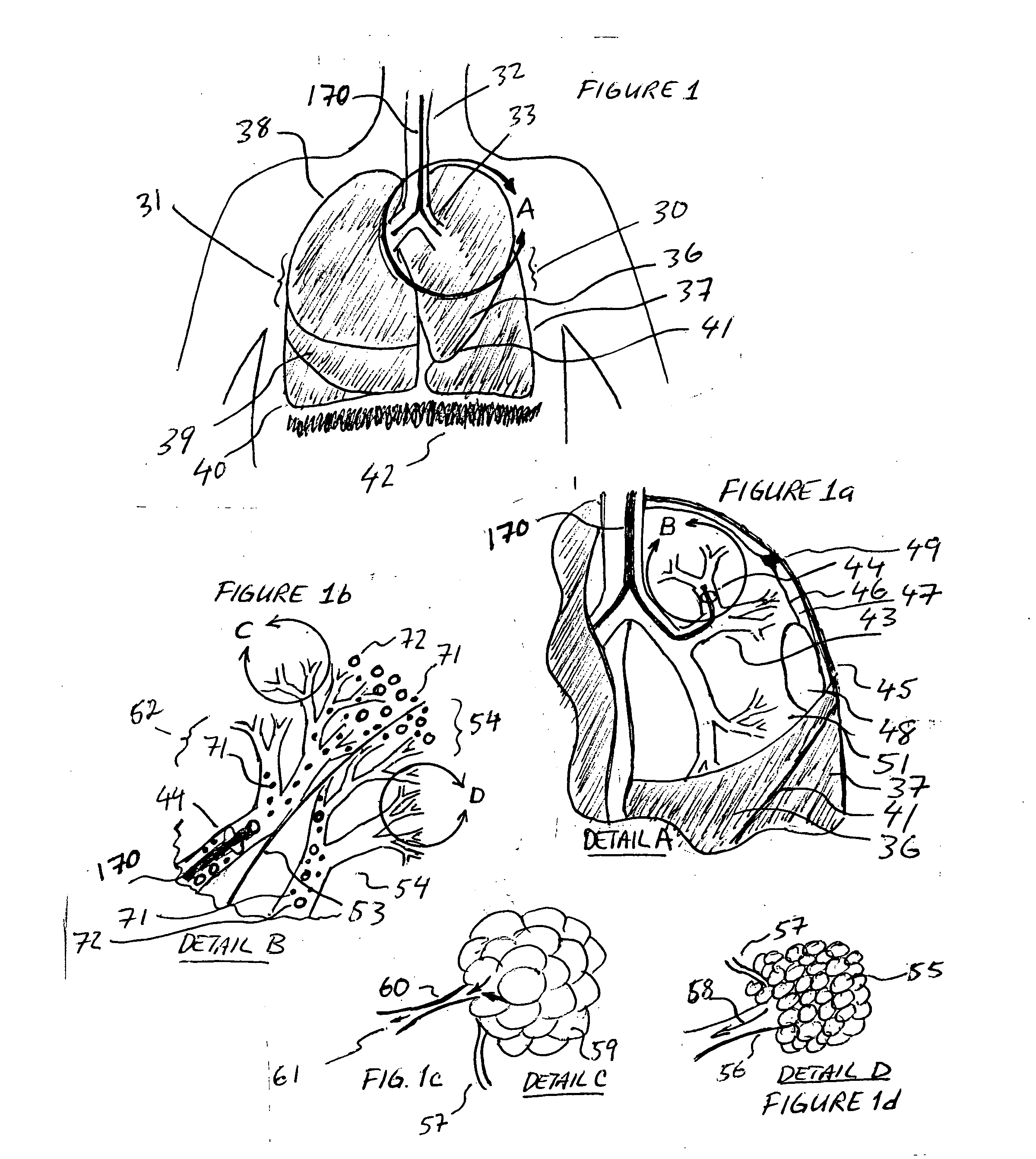
[0057] Referring to FIG. 1 the lung anatomy is described including the left 30 and right 31 lung, trachea 32, the left main stem bronchus 33, the five lung lobes 36, 37, 38, 39, 40, a lateral fissure 41 separating the left upper and lower lobe, and the diaphragm 42 which is displaced downward indicative of a hyperinflated emphysematous lung. FIG. 1a shows a cut away view of the left upper lobe bronchus 43, the apical segmental bronchus 44 of the left upper lobe, the parietal pleura 45, the visceral pleura 46 and the pleural cavity 47. Large bulla 48 are membranous air vesicles created on the surface of the lung between the visceral pleura 46 and lung parenchyma 51 due to leakage of air out of the damaged distal airways and through the lung parenchyma. The air in the bullae is highly stagnant and does not easily communicate with the conducting airways making it very difficult to collapse bullae. Pleural adhesions 49 are fibrous tissue between the visceral pleura 46 and the parietal p...


PUM


Abstract

Methods, systems and devices are described for new modes of ventilation in which specific lung areas are ventilated with an indwelling trans-tracheobronchial catheter for the purpose of improving ventilation and reducing hyperinflation in that specific lung area, and for redistributing inspired air to other healthier lung areas, for treating respiratory disorders such as COPD, ARDS, SARS, CF, and TB. Trans-Tracheobronchial Segmental Ventilation (TTSV) is performed on either a naturally breathing or a mechanical ventilated patient by placing a uniquely configured indwelling catheter into a bronchus of a poorly ventilated specific lung area and providing direct ventilation to that area. The catheter can be left in place for extended periods without clinician attendance or vigilance. Ventilation includes delivery of respiratory gases, therapuetic gases or agents and evacuation of stagnant gases, mixed gases or waste fluids. Typically the catheter's distal tip is anchored without occluding the bronchus but optionally may intermittently or continuously occlude the bronchus. TTSV is optionally performed by insufflation only of the area, or by application of vacuum to the area, can include elevating or reducing the pressure in the targeted area to facilitate stagnant gas removal, or can include blocking the area to divert inspired gas to better functioning areas.

Description

CROSS REFERENCE TO RELATED APPLICATIONS [0001] This application claims Provisional Patent Application No. 60 / 479,213 as a predicate application with the respective priority filing date of Jun. 18, 2003.STATEMENT REGARDING FEDERALLY SPONSORED RESEARCH OR DEVELOPMENT [0002] Not Applicable DESCRIPTION OF ATTACHED APPENDIX [0003] Not Applicable GOVERNMENT INVENTION OR CONTRACT WITH GOVERNMENT [0004] None ENTITY [0005] Small Entity Concern PRIOR ART [0006] U.S. Pat. Nos. 4,825,859; 4,838,255; 4,850,350; 4,967,743; 5,000,175; 5,134,996; 5,186,167; 5,193,533; 5,255,675; 5,460,613; 5,513,628; 5,598,840; 5,791,337; 5,904,648; 6,227,200; 6,520,183; 6,575,944; 6,575,944; U.S. Published Patent Applications: 20010035185; 20020179090. OTHER RELATED APPLICATIONS [0007][0007] Fink J. B.; Helium-oxygen: An Old Therapy Creates New Interest. (J Resp Care Pract April 1999; 71-76) [0008] Christopher K L et al.; Transtracheal oxygen for refractory hypoxemia. (JAMA 1986; 256: 494-7) [0009] Gaebek J. B. et...

Claims


Application Information

Patent Timeline
Patent Type & Authority Applications(United States)
IPC IPC(8): A61M16/00A61M16/04A61M16/06A61M16/10
CPCA61M16/04A61M16/0672A61M16/0465A61M16/10A61M2016/0021A61M2205/8225A61M2209/06A61M2230/432A61M16/0009A61M16/0404A61M16/042A61M16/0445A61M16/0459A61M16/0486A61M16/0434A61M16/0012A61M2016/103
Inventor WONDKA, ANTHONY DAVID
Owner BREATHE TECHNOLOGIES INC
Why Eureka
Try Eureka