
Low temperature interconnection of nanoparticles

a nanoparticle and nanoparticle technology, applied in the direction of sustainable manufacturing/processing, conductors, final product manufacturing, etc., can solve the problems of limiting the manufacturing to batch processes, the application to those tolerant of rigid structure, and the increase of the cost of manufacturing a photovoltaic cell, so as to achieve better performance

Inactive Publication Date: 2005-01-27
CHITTIBABU KETHINNI +1
View PDF99 Cites 29 Cited by
  • Summary
  • Abstract
  • Description
  • Claims
  • Application Information

AI Technical Summary

Benefits of technology

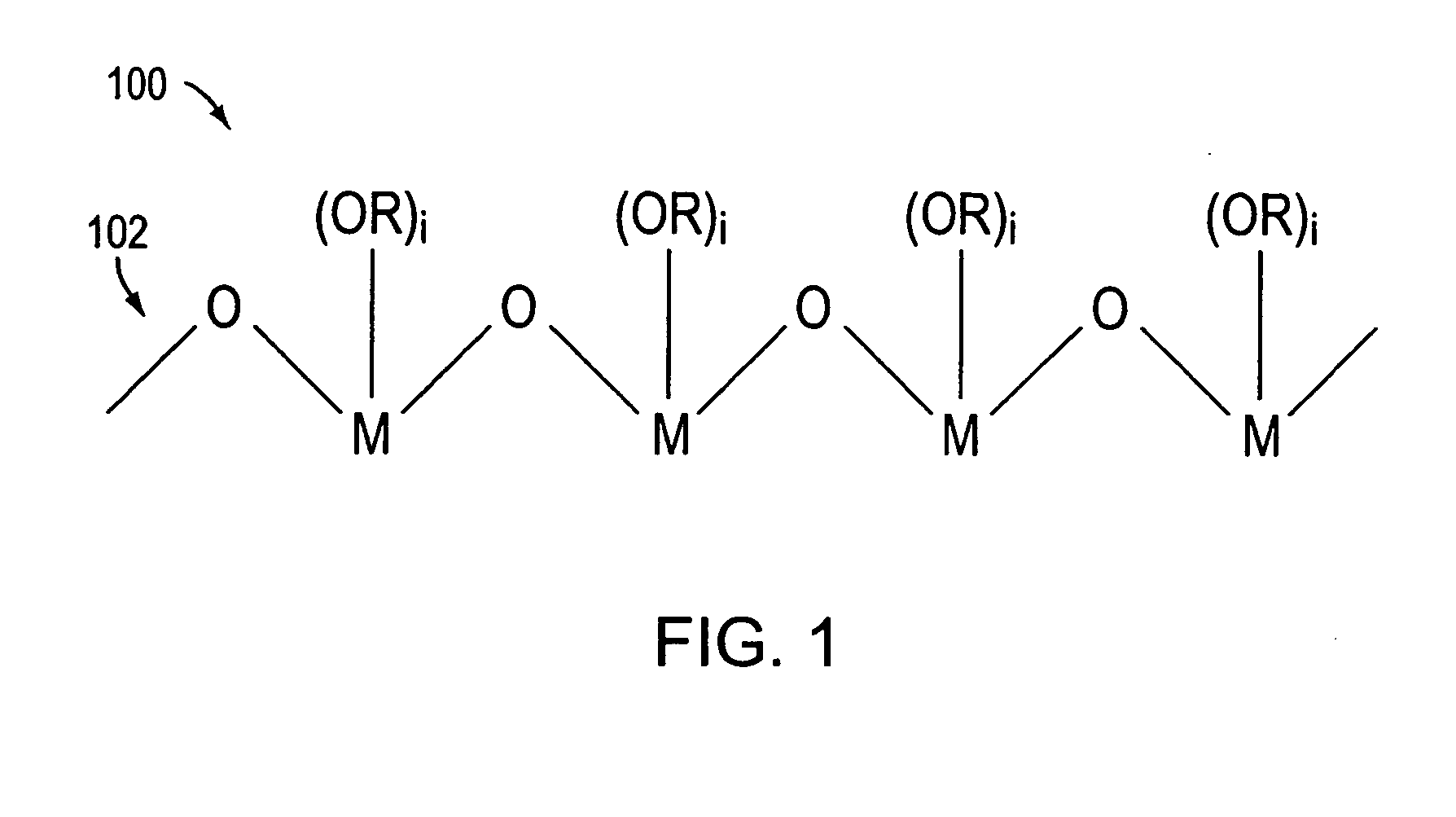
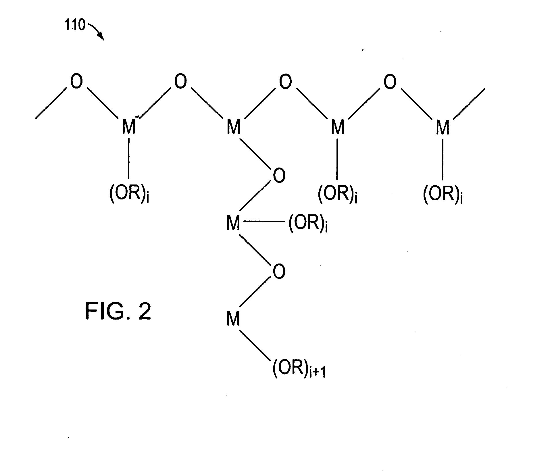
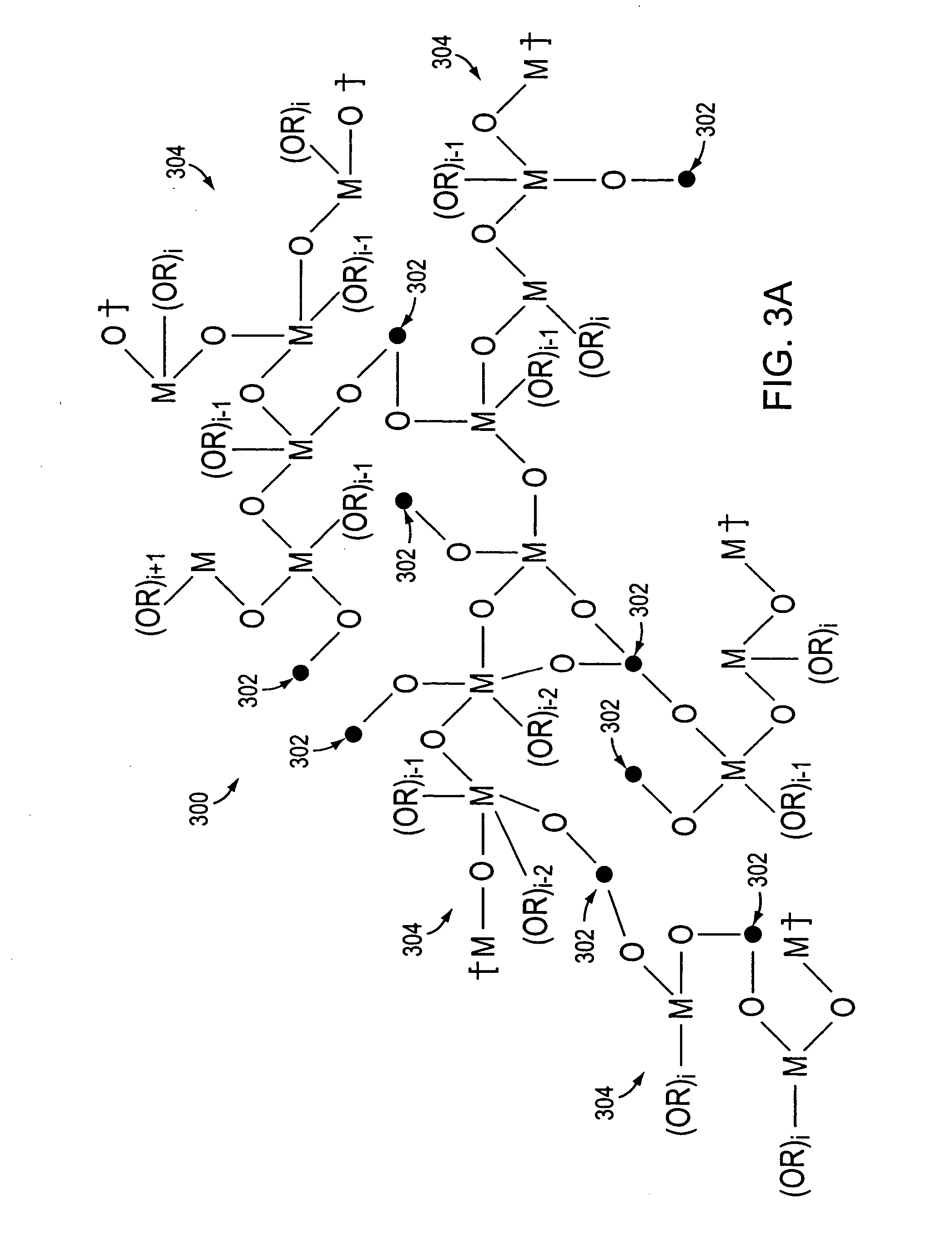
The invention in, one embodiment, addresses the deficiencies of the prior art by providing a polymeric linking agent that enables the fabrication of thin film solar cells at relatively low temperatures. This enables the manufacture of such cells on flexible substrates, including, for example, those substrates constructed from somewhat heat sensitive polymeric materials. In addition, the invention provides photovoltaic cells and methods of photovoltaic cell fabrication that facilitate their manufacture by a relatively simple, continuous manufacturing process. For example, a roll-to-roll process can be utilized instead of the batch processes that limited the prior art. More particularly, in one embodiment, the invention provides a method for interconnecting metal oxide nanoparticles in DSSCs, with reduced or no heating, using a polymeric linking agent. By way of example, metal oxide nanoparticles may be interconnected by contacting the nanoparticles with a suitable polymeric linking agent dispersed in a solvent, such as n-butanol, at about room temperature or at elevated temperatures below about 300° C.
In one embodiment of the photovoltaic cell, at least one of the first and second flexible, significantly light transmitting substrates includes a transparent substrate (e.g., a polyethylene terephthalate material). In another embodiment, the photovoltaic cell includes a catalytic media layer disposed between the first and second flexible, significantly light transmitting substrates. The catalytic media layer is, for example, platinum. In another embodiment, the photovoltaic cell includes an electrical conductor material disposed on at least one of the first and second flexible, significantly light transmitting substrates. In another embodiment, the electrical conductor material is, for example, indium tin oxide.

Problems solved by technology

Although the photovoltaic cells of Grätzel are fabricated from relatively inexpensive raw materials, the high temperature sintering technique used to make these cells limits the cell substrate to rigid transparent materials, such as glass, and consequently limits the manufacturing to batch processes and the applications to those tolerant of the rigid structure.
Furthermore, the high temperature sintering process increases the cost of manufacturing a photovoltaic cell due to the energy required to perform the sintering.

Method used


Image

  • Low temperature interconnection of nanoparticles
  • Low temperature interconnection of nanoparticles
  • Low temperature interconnection of nanoparticles

Examples


example 1

Dip-Coating Application of Polylinker

In this illustrative example, a DSSC was formed as follows. A titanium dioxide nanoparticle film was coated on a SnO2:F coated glass slide. The polylinker solution was a 1% (by weight) solution of the poly(n-butyl titanate) in n-butanol. In this embodiment, the concentration of the. polylinker in the solvent was preferably less than 5% by weight. To interconnect the particles, the nanoparticle film coated slide was dipped in the polylinker solution for 15 minutes and then heated at 150° C. for 30 minutes. The polylinker treated TiO2 film was then photosensitized with a 3×10⁻⁴ N3 dye solution for 1 hour. The polylinker treated TiO2 film coated slide was then fabricated into a 0.6 cm2 photovoltaic cell by sandwiching a triiodide based liquid redox electrolyte between the TiO2 film coated slide a platinum coated SnO2:F glass slide using 2 mil SURLYN 1702 hot melt adhesive available from DuPont. The platinum coating was approximately 60 nm thick. T...

example 2

Polylinker-Nanoparticle Solution Application

In this illustrative example, a 5.0 mL suspension of titanium dioxide (P25, which is a titania that includes approximately 80% anatase and 20% rutile crystalline TiO2 nanoparticles and which is available from Degussa-Huls) in n-butanol was added to 0.25 g of poly(n-butyl titanate) in 1 mL of n-butanol. In this embodiment, the concentration of the polylinker in the polylinker-nanoparticle solution was preferably less than about 50% by weight. The viscosity of the suspension changed from milk-like to toothpaste-like with no apparent particle separation. The paste was spread on a patterned SnO2:F coated glass slide using a Gardner knife with a 60 μm thick tape determining the thickness of wet film thickness. The coatings were dried at room temperature forming the films. The air-dried films were subsequently heat treated at 150° C. for 30 minutes to remove solvent, and sensitized overnight with a 3×10⁻⁴ M N3 dye solution in ethanol. The sens...

example 3

DSSC Cells Formed without Polylinker

In this illustrative example, an aqueous titanium dioxide suspension (p25) containing about 37.5% solid content was prepared using a microfluidizer and was spin coated on a fluorinated SnO2 conducting electrode (15 Ω / cm2) that was itself coated onto a coated glass slide. The titanium dioxide coated slides were air dried for about 15 minutes and heat treated at 150° C. for 15 minutes. The slides were removed from the oven, cooled to about 80° C., and dipped into 3×10⁻⁴ M N3 dye solution in ethanol for about 1 hour. The sensitized titanium dioxide photoelectrodes were removed from dye solution rinsed with ethanol and dried over a slide warmer at 40° C. The sensitized photoelectrodes were cut into small pieces (0.7 cm×0.5-1 cm active area) and sandwiched between platinum coated SnO2:F-transparent conducting glass slides. A liquid electrolyte containing 1 M LiI, 0.05 M iodine, and 1 M t-butyl pyridine in 3-methoxybutyronitrile was applied between th...


PUM

PropertyMeasurementUnit
Fractionaaaaaaaaaa
Sizeaaaaaaaaaa
Sizeaaaaaaaaaa

Abstract

A polymeric linking agent enables the manufacture of photovoltaic cells on flexible substrates, including, for example, polymeric substrates. Photovoltaic cells may be fabricated by a relatively simple continuous manufacturing process, for example, a roll-to-roll process, instead of a batch process.

Description

FIELD OF THE INVENTION The invention relates generally to the field of photovoltaic devices, and more specifically to chemical structures and methods of interconnecting nanoparticles at low temperatures. BACKGROUND OF THE INVENTION Thin film solar cells composed of percolating networks of liquid electrolyte and dye-coated sintered titanium dioxide were developed by Dr. Michael Grätzel and coworkers at the Swiss Federal Institute of Technology. These photovoltaic devices fall within a general class of cells referred to as dye-sensitized solar cells (“DSSCs”). Conventionally, fabrication of DSSCs requires a high temperature sintering process (>about 400° C.) to achieve sufficient interconnectivity between the nanoparticles and enhanced adhesion between the nanoparticles and a transparent substrate. Although the photovoltaic cells of Grätzel are fabricated from relatively inexpensive raw materials, the high temperature sintering technique used to make these cells limits the cell s...

Claims


Application Information

Patent Timeline
IPC IPC(8): H01L31/04A61K9/14A61K33/24B32B19/00D02G3/44H01B1/00H01G9/00H01G9/20H01L31/00H01L31/0352H01L31/05H01M6/00H01M14/00H10K99/00
CPCH01G9/2031H01G9/2059H01G9/2068Y02E10/542H01G9/2095H01L51/0086H01G9/2086Y02P70/50H10K85/344
Inventor CHITTIBABU, KETHINNIGAUDIANA, RUSSELL
Owner CHITTIBABU KETHINNI
Learn More