Steam reforming of solid carbon in protonic ceramic fuel cells

Active Publication Date: 2005-01-27
PROTONETICS INT
View PDF27 Cites 6 Cited by
  • Summary
  • Abstract
  • Description
  • Claims
  • Application Information

AI Technical Summary

Benefits of technology

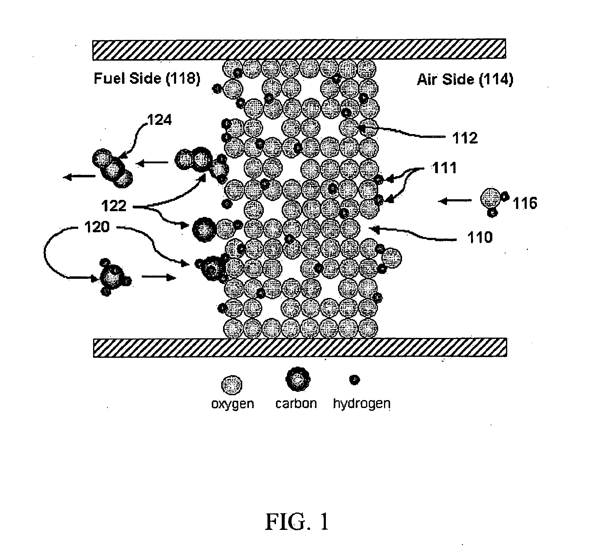
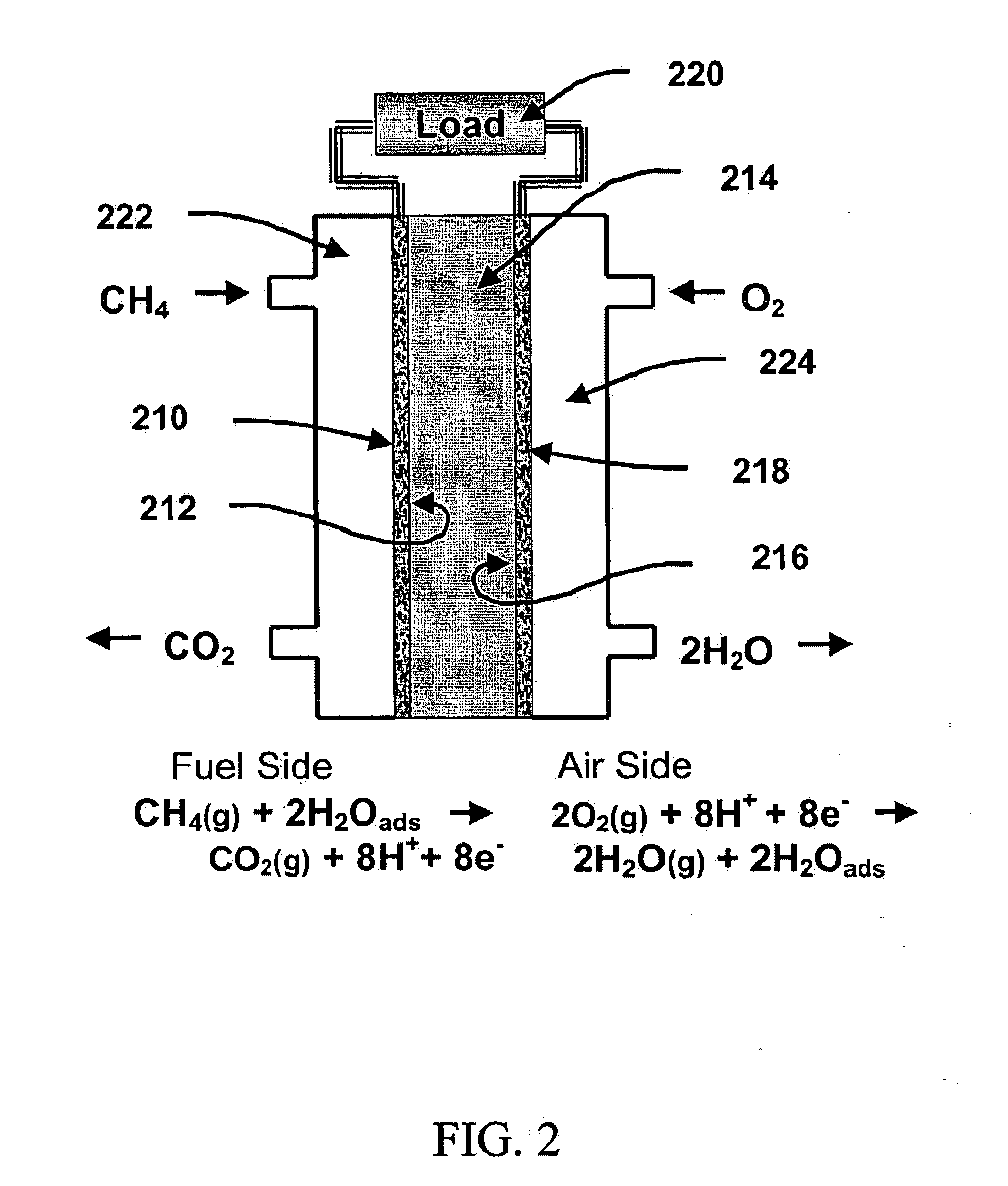
In the process of steam permeation reforming, water vapor that appears at the fuel side by steam permeation through the electrolyte is consumed in reactions with the hydrocarbon molecules to produce hydrogen and carbon monoxide (CO) by reaction (1.1) and hydrogen and carbon dioxide (CO2) by reaction (1.2). Since the partial pressure gradient of water vapor across the protonic ceramic membrane determines the steam permeation rate, the appearance of water vapor at the fuel side for reaction with the hydrocarbon fuels is self-regulating, so that only as much water vapor as is required for the reforming of hydrocarbons is delivered. That is, any excess water vapor that appears at the fuel side dynamically reduces the water vapor partial pressure gradient, and thus, reduces the flux of water molecules through the membrane. Also, in this process, the water vapor available at the fuel side by permeation reduces or eliminates the propensity of hydrocarbons at the anode to pyrolyze into carbon residue (i.e., coking) since an absorbed layer of water vapor is always present on the surface of the catalyst whenever a gaseous hydrocarbon molecule arrives. Also, steam permeation occurs independently of whether or not the cell is delivering current to an external load, so coking is obviated even at open circuit.
Hydrogen produced at the fuel side by the reaction of steam with hydrocarbons by reaction (1.1) or with carbon monoxide by reaction (1.2) is adsorbed on the surface, and enters the anode by electrochemical oxidation to produce electrons and hydrogen ions. The electrons flow through an external load, and the hydrogen ions (protons) traverse the electrolyte by hopping from oxygen site to oxygen site, by the so-called Grotthuss mechanism. It is these protons that carry the Faradaic current through the ceramic membrane when the fuel cell is operating under load. These protons are electrochemically combined at the cathode with oxygen (typically from air) and electrons coming from the external load to produce water vapor and electric power. For example, four molecules of H2O are produced at the cathode for every methane molecule consumed at the anode (assuming the carbon is completely oxidized to CO2). Under steady state conditions, two of these water molecules permeate back to the fuel side for subsequent reforming, and the remaining two water molecules are expelled from the cell as exhaust. Since dry hydrocarbon fuels are supplied directly to the fuel cell, high thermodynamic efficiency is obtained. Since any hydrogen produced at the anode is transported to the air side when current is flowing through the external circuit, reaction equilibrium is shifted strongly toward CO2 production when the fuel cell is operating under load. Since CO2 is the only exhaust gas produced at the anode, high fuel utilization is possible with this design.
In a further embodiment, the metallic cathode is stable against oxidation and corrosion in moist, oxidizing atmospheres at elevated temperatures. For example, the cathode can be a platinum, high nickel alloy, or mixed protonic / electronic conducting ceramic cathode less than about 20 microns in thickness applied to the opposing side of the electrolyte, and capable of operating at temperatures less than about 850° Celsius.

Problems solved by technology

In practice, however, some of the energy is always “lost” irreversibly as heat and unused fuel.
Most fuel cells designed to operate directly on hydrocarbon fuels suffer from poor fuel utilization.
High temperature fuel cells operating directly on hydrocarbon fuels are plagued by the propensity of hydrocarbons to pyrolize spontaneously on the catalyst into atomic carbon and hydrogen.
These carbon deposits foul, and eventually destroy, the cell.
These fuel cells have the advantage of higher thermodynamic efficiency and greater simplicity than other intermediate and high temperature fuel cells, but still suffer from the problems of coking and poor fuel utilization.

Method used


Image

  • Steam reforming of solid carbon in protonic ceramic fuel cells
  • Steam reforming of solid carbon in protonic ceramic fuel cells
  • Steam reforming of solid carbon in protonic ceramic fuel cells

Examples


examples

A series of experiments were performed that involved measuring the current and voltage of single cells as a function of temperature and elapsed time with various hydrocarbon fuels. The cells were typically operated at temperatures ranging from 600° C. to 850° C. Numerous cells were tested with different electrolyte thicknesses and electrode metals, but otherwise nearly identical construction. In all of the experiments, the cells consisted of an anode, a cathode, and a 23 millimeter diameter 10% yttrium-doped barium cerate, BCY10, ceramic electrolyte disc. The electrolyte thickness ranged from 0.2 millimeters to 1.0 millimeter. All of the cells tested were of the electrolyte-supported type.

A detailed description of one of the experiments, that is typical of many other experiments performed is as follows: A disc of BCY10 protonic ceramic electrolyte was prepared by the traditional powder compaction and sintering method, using powder obtained from Praxair Specialty Ceramics. The dis...


PUM


Abstract

A process for converting a carbon containing fuel and water vapor into a reformate gas that includes hydrogen, carbon monoxide and carbon dioxide, using water molecules that diffuse through a membrane by steam permeation reforming. The process includes providing a ceramic membrane comprising an oxide ceramic having intrinsic and extrinsic oxygen ion vacancies, and having first and second surfaces; where the oxide ceramic capable of reacting with gaseous water molecules at the first surface by the reversible reaction, H2O(g)+VO••+OxO2OH•o; and the oxide ceramic capable of producing gaseous water molecules at the second surface by the reversible reaction, 2 OH•oH2O(g)+VO••+Oxo; contacting water vapor with the first surface; contacting the reformate gas with the second surface, whereby solid state ambipolar diffusion of oxygen ion vacancies and protons across the membrane occurs; and the ambipolar diffusion produces a net diffusion flux of water molecules through the membrane from the first surface to the second surface.

Description

FIELD OF THE INVENTION This application relates generally to a process that uses solid state ambipolar diffusion of protons and oxygen ion vacancies in protonic ceramic membranees to reform hydrocarbon fuels, called “steam permeation reforming”, and more specifically to a protonic ceramic fuel cell that utilizes steam permeation reforming of hydrocarbon fuels to produce electric power. BACKGROUND OF THE INVENTION One of the advantages of fuel cells is that they can, in principle, convert the chemical energy of fuels directly into electrical energy at high efficiencies. In practice, however, some of the energy is always “lost” irreversibly as heat and unused fuel. Since the electric power is the most valuable output, one of the most important characteristics of a fuel cell design is the percentage of the available energy of the fuel that is converted into electricity. High electrical conversion efficiency requires that both the thermodynamic efficiency and fuel utilization be high....

Claims


Application Information

Patent Timeline
IPC IPC(8): B01D71/02C01B5/00C10J3/18H01M2/00H01M2/02H01M8/00H01M8/04H01M8/06H01M8/10H01M8/12H01M8/16H01M8/24
CPCB01D71/024C01B5/00C10J3/18C10J2300/0916C10J2300/093C10J2300/0973Y02E60/525C10J2300/1671H01M8/0612H01M8/0625H01M8/0643H01M2008/1293Y02E60/50C10J2300/1646Y02P20/145B01D71/0271
Inventor COORS, W. GROVER
Owner PROTONETICS INT
Why Eureka
Try Eureka