Microfluidic ser(r)s detection

a microfluidic and ser(r) technology, applied in the field of microfluidic, can solve the problems of macro-flow cell based systems, difficult to produce reproducible serrs substrates, and generally not being able to take samples, and achieve the effect of effective code based particles and easy identification

Inactive Publication Date: 2005-02-24
UNIV OF STRATHCLYDE +1
View PDF3 Cites 57 Cited by
  • Summary
  • Abstract
  • Description
  • Claims
  • Application Information

AI Technical Summary

Benefits of technology

[0053] Embodiments of the present invention relate to the ability to selectively code particles. For example it is possible to attach a number of different SER(R)S reactive dyes to the surface of a colloid particle as well as a reagent, such as a protein, peptide or oligonucleotide designed to bind to the analyte to be detected. This can be done either prior to introduction of the particle to the device or in situ in the dvice. By virtue of being able to effectively code the particles based on the particular dyes used, it is possible to detect analyte based on the particular SER(R)S signal generated. Complex mixtures of differently coded particles can be provided and

Problems solved by technology

One of the main problems associated with using SERRS as a quantitative analytical technique is the difficulty associated with producing reproducible SERRS substrates.
However, as with other substrates, there is still a problem associated with the production of stable, reproducible silver colloids(10, 14).
However, there are a number of potential disadvantages with using macro-flow cell based systems.
It is not generally possible therefore to take a sample and carry out the SERRS detection

Method used


Image

  • Microfluidic ser(r)s detection
  • Microfluidic ser(r)s detection
  • Microfluidic ser(r)s detection

Examples


example 1

Device Fabrication

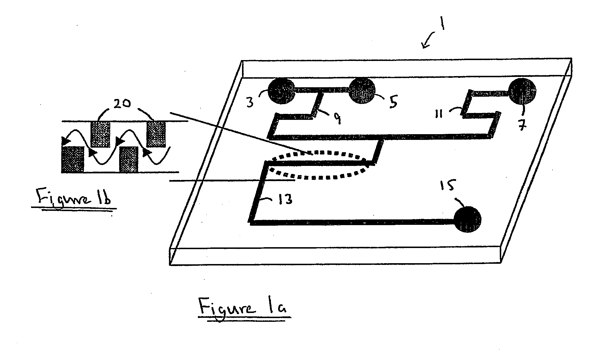
[0073] The fluid channel was fabricated by a standard photolithographic technique. S1818 photoresist (Shipley Europe, Coventry, UK) was spin coated on an acid cleaned 1.5 mm thick soda lime glass (Soda Lime glass, Nanofilm, USA) at 4000 rpm for 30 seconds. The glass was baked on a 90° C. hot plate for 3 minutes, followed by UV exposure through an acetate sheet lithography mask to define the channel pattern for 8 seconds. The photoresist was developed in a mixed solution of 1 part of Microposit Developer Concentrate (Shipley Europe) and 1 part of RO water for 35 seconds and dried with nitrogen. The substrate was then baked on a 90° C. hot plate for 15 minutes to ensure all the solvent had been evaporated and to harden the photoresist. Finally, the glass was wet etched in a mixed solution of 1 part of hydrofluoric acid and 4 parts of RO water for 15 minutes, resulting in 30 μm deep and 250 μm wide channel. After the etching procedure, the glass was ultrasonicated in...

example 2

Use of the Device and SERRB Detection

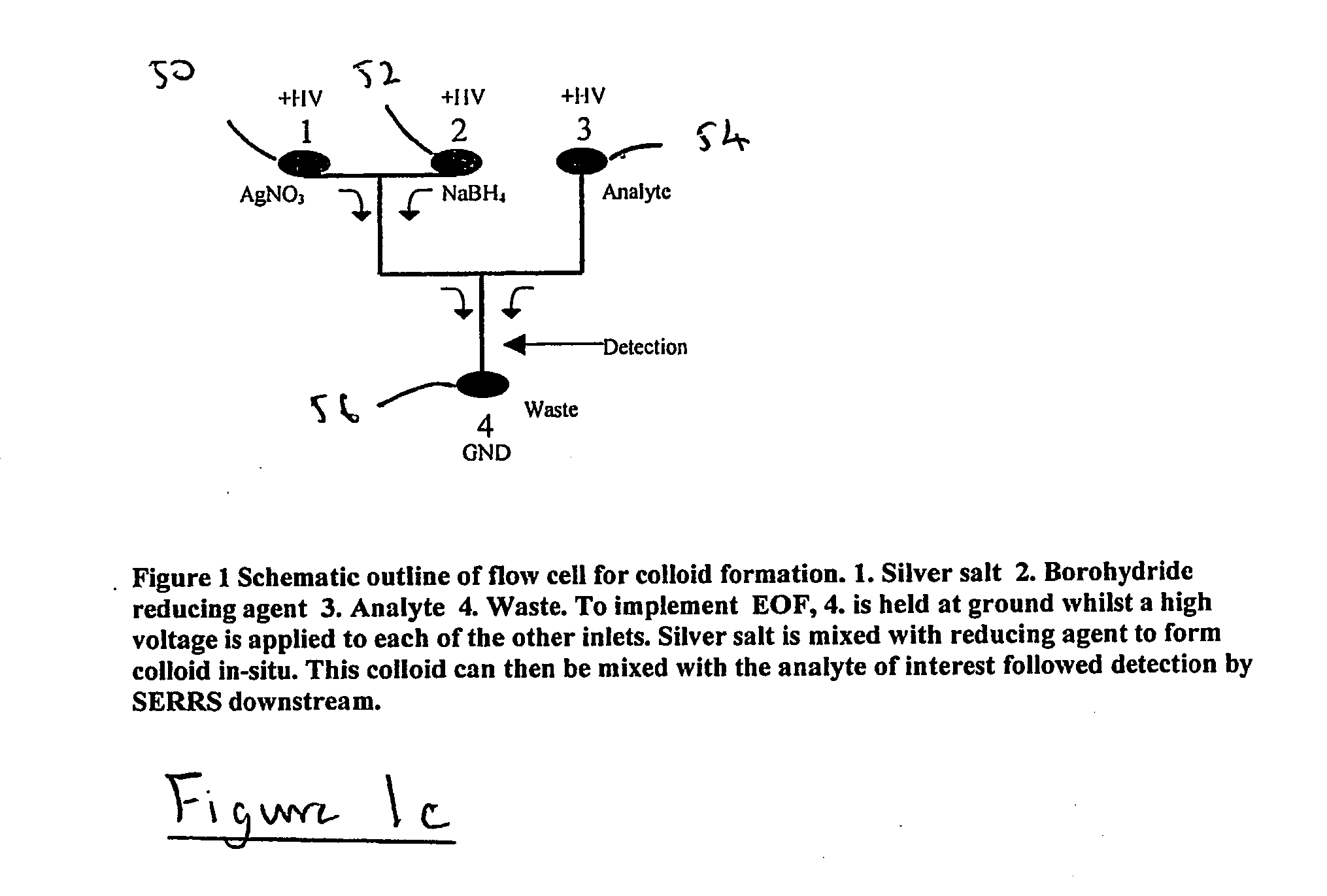
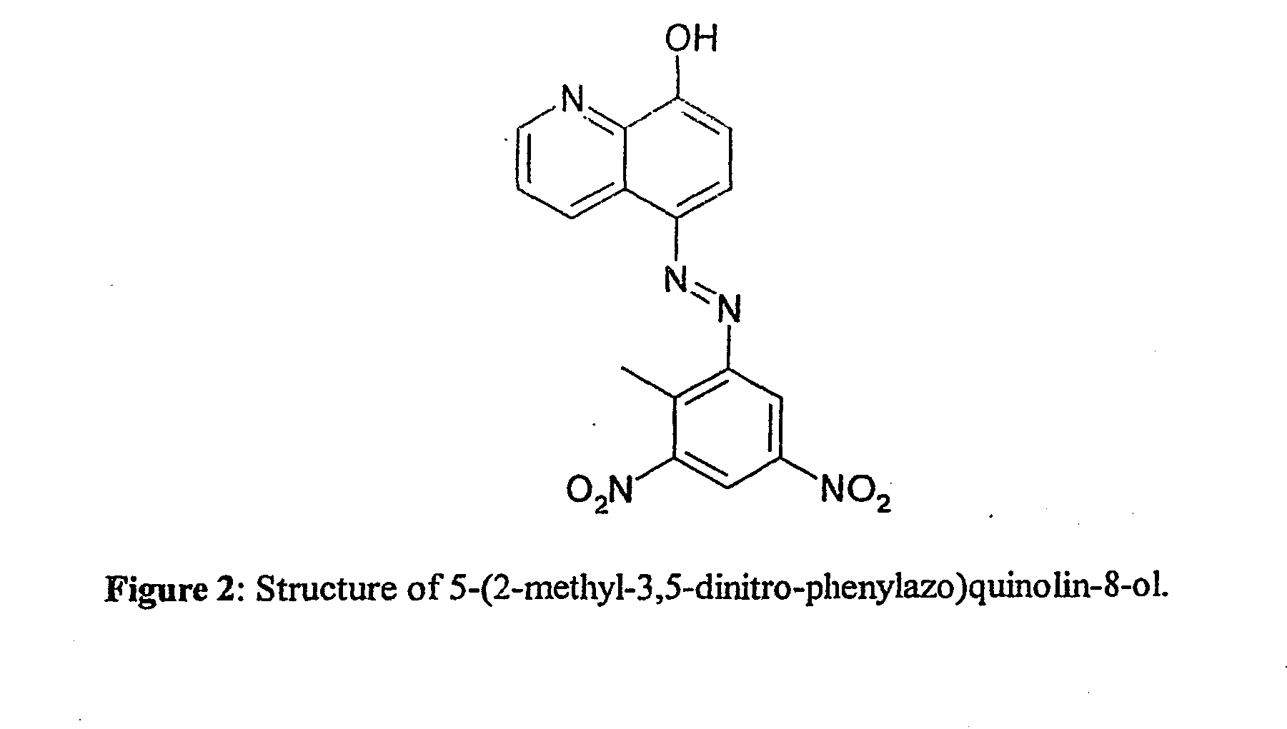
[0077] Sodium borohydride (99%), silver nitrate (99.9999%) and sodium hydroxide (97%) were purchased from Aldrich (Dorset, England). An aqueous solution of silver nitrate (2.6×10⁻³ M) and a solution of sodium borohydride (1.1×10⁻³ M) in sodium hydroxide solution (0.1 M), were introduced into inlets 3 and 5 respectively using a micropipette. The azo dye solution, which was prepared in methanol, was introduced into inlet 7. The chosen analyte was an azo dye, 5-(2-methyl-3,5-dinitro-phenylazo)quinolin-8-ol, synthesised as part of a program to detect trinitrotoluene (TNT) by derivatisation methods. It was analysed by nmr and C,H and N analysis and found to be pure (C was within 0.4%). The structure of the dye is shown in FIG. 2.

[0078] The solutions were pulled through the system under vacuum using a syringe attached to outlet 15. Spectra were accumulated by focussing the laser on the colloid stream using a ×10 objective lens. Accumulation times wer...

example 3

Coded Nanoparticles for Detection of DNA by SERRS

[0093] Here it is shown that a labelled oligonucleotide can be detected with three other dyes in a suspension of nanoparticles indicating the ability to provide a coded nanoparticle for identification of a particular sequence in a mixture of DNA fragments.

[0094] The oligonucleotide examined contained a basic priming sequence of 5′ GTG CTG CAG GTG TAA ACT TGT ACC AG 3′. The visible chromophore used was the fluorophore 2,5,2′,4′,5′,7′-hexachloro-6-carboxyfluorescein (HEX), which was attached at the 5′ terminus. HEX is negatively charged and therefore repels the negatively charged metal surface. Surface attachment was achieved by the incorporation of positively charged modified nucloebases at the 5′-terminus next to the HEX label. The three dyes used were azos containing the benzotriazole group for surface attachment.

[0095] All spectra were acquired in a Renishaw 2000 Raman Microprobe with a charge-coupled device (CCD) spectrometer. T...


PUM

PropertyMeasurementUnit
Flow rateaaaaaaaaaa
Sizeaaaaaaaaaa
Shapeaaaaaaaaaa

Abstract

The present invention relates to a microfluidic method of generating in situ a colloid for use in detecting an an using for example SER(R)S, as well as a method of detecting an analyte using SER(R)S in a microfluidic system. The invention also relates to microfluidic devices for use in detecting analytes such as by way of SER(R)S signals.

Description

BACKGROUND TO THE INVENTION [0001] The present invention relates to a microfluidic method of generating in situ a colloid for use in detecting an analyte using for example SER(R)S, as well as a method of detecting an analyte using SER(R)S in a microfluidic system. The invention also relates to microfluidic devices for use in detecting analytes such as by way of SER(R)S signals. [0002] Surface-enhanced resonance Raman scattering(1,2) is an extremely powerful analytical tool which not only yields information about the molecular structure of the analyte in the form of a vibrational spectrum, but also allows sensitivity comparable to that achieved using fluorescence spectroscopy(3-5). Surface enhanced Raman scattering(SERS) involves the adsorption of an analyte on a suitable surface(usually roughened silver or gold) and the recording of the Raman scattering from that surface. The use of molecular resonance enhancement, where the frequency of the excitation source is tuned to be in reson...

Claims


Application Information

Patent Timeline
IPC IPC(8): B01F5/06B01F13/00B01J13/00B01L3/00C12Q1/68G01N33/53G01N33/543G01N35/00G01N35/08
CPCB01F5/061B01F13/0059G01N2035/00237G01N35/08B01F2005/0621B01F2005/0636B01J13/0043B01L3/502769B01L2300/0816B01L2300/0867B01L2300/1822B01L2400/0415B01L2400/0487C12Q1/6816G01N33/54373C12Q2565/632C12Q2565/629B01F25/4317B01F25/431B01F25/431971B01F33/30
Inventor SMITH, WILLIAM EWENGRAHAM, DUNCANCOOPER, JONATHAN MARKKEIR, RUTHIGATA, EISHI
Owner UNIV OF STRATHCLYDE
Why Eureka
Try Eureka