Lithium secondary battery comprising fine fibrous porous polymer membrane and fabrication method thereof

Inactive Publication Date: 2005-03-10
SAMSHIN CREATION
View PDF0 Cites 60 Cited by
  • Summary
  • Abstract
  • Description
  • Claims
  • Application Information

AI Technical Summary

Benefits of technology

[0022] It is another object of the present invention to provide a lithium secondary battery having improved energy density, cycle characteristics, low- and high-temperature characteristics, high-rate discharge characteristics and stability in comparison with those of the conventional lithium secondary battery.
[0023] It is still another object of the present invention to provide a fabrication method of a lithium secondary battery by a simple process, which is suitable to scale-up of a battery.

Problems solved by technology

However, the cycle characteristic of the secondary battery using metallic lithium or a lithium alloy is low due to the dendrite formed on the anode as a result of repeated charging and discharging of the battery.
Since a lithium ion battery was developed by SONY Company in Japan, it has been widely used around the world; however, those using PE or PP separator have problems such as instability of the battery, intricacy of its fabrication process, restriction on battery shape and limitation of high capacity.
A conventional polymer electrolyte is mainly prepared with polyethylene oxide (hereinafter referred to as “PEO”) as polymer matrix, but its ionic conductivity is merely 10−8 S / cm at room temperature, and accordingly it can not be commercialized.
However, such polymer electrolyte has a problem in that its mechanical stability, namely, its strength, is low because the electrolyte is a little bit soft.
Especially, such low mechanical strength may cause many problems in fabrication of electrodes and batteries.
However, it is not suitable for a lithium polymer battery because its mechanical strength is very poor.
In addition, a polyvinylchloride (hereinafter referred to as “PVC”) based polymer electrolyte having good mechanical strength and ionic conductivity of 10−3 S / cm at room temperature has been reported in J. Electrochem. Soc., 140, L96 (1993) by M. Alamgir and K. M. Abraham. However, its low-temperature characteristics are poor and its contact resistance is high.
However, it has a disadvantage in that its fabrication process is intricate because in preparation of the polymer electrolyte, it is necessary to extract plasticizer contained in a polymer matrix in order to obtain a nanoporous matrix.
In addition, if the plasticizer is not been completely extracted, remained plasticizer can cause weaken characteristics of the battery.
Further, it has a serious disadvantage that an additional lamination process is required in fabrication of electrodes and batteries, because its adhesive force is poor, while its mechanical strength is good.
However, in the method (1), if an ultra-fine fibrous porous polymer membrane is weaker than a PE or PP film in mechanical strength, there might be a problem in fabrication of a lithium secondary battery.
In the meantime, in the method (2), electrodes may be damaged by a solvent contained in the polymer solution.
Besides, in a lithium secondary battery fabricated by the method (1) or (2), adhesive force between a fibrous membrane is weak to some extent, it is necessary to improve this problem.

Method used


Image

  • Lithium secondary battery comprising fine fibrous porous polymer membrane and fabrication method thereof
  • Lithium secondary battery comprising fine fibrous porous polymer membrane and fabrication method thereof
  • Lithium secondary battery comprising fine fibrous porous polymer membrane and fabrication method thereof

Examples


example 1

Preparation of a Separator / Electrode Composite in Which an Ultra-Fine Fibrous Porous Polymer Membrane is Combined onto the Electrode

example 1-1

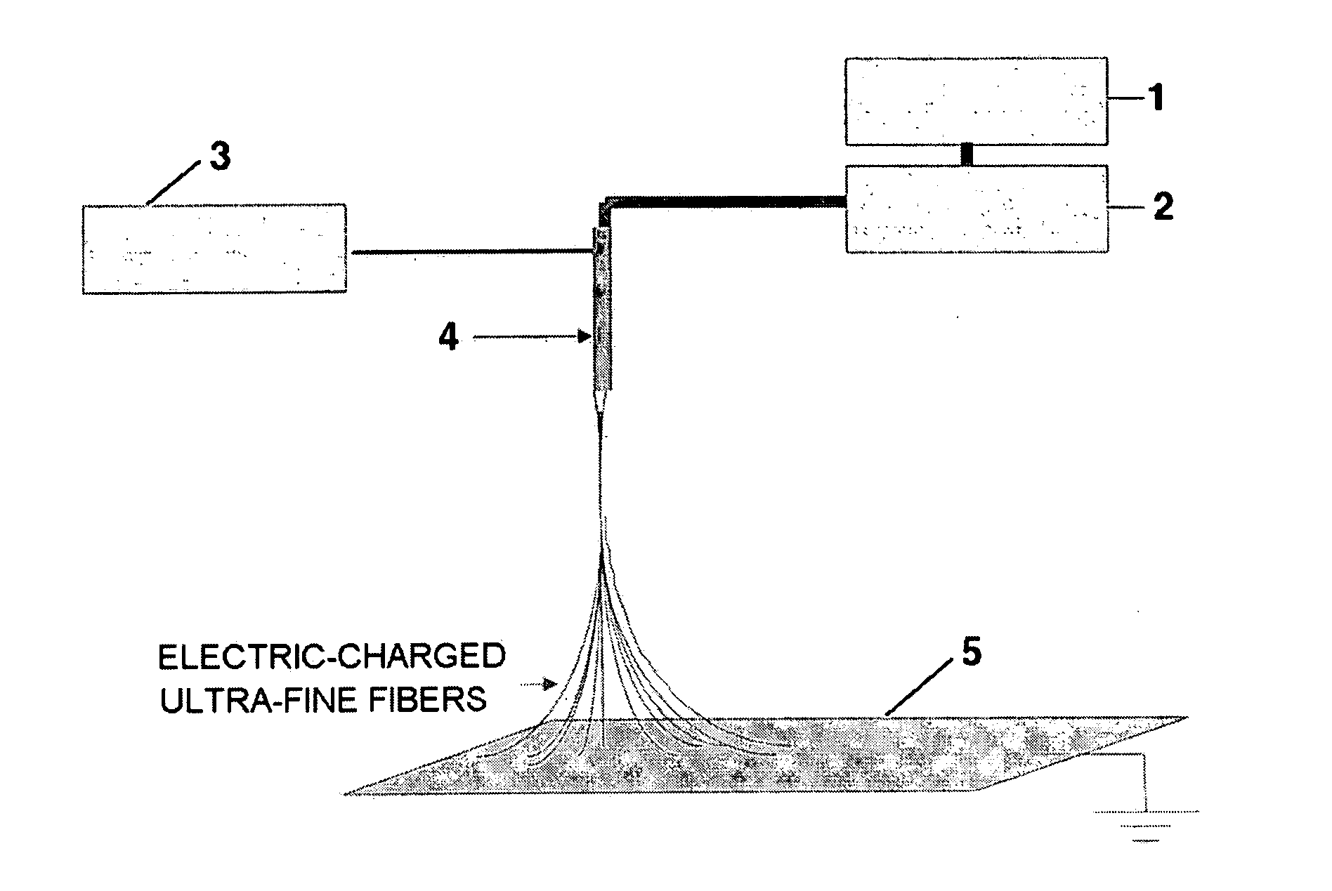
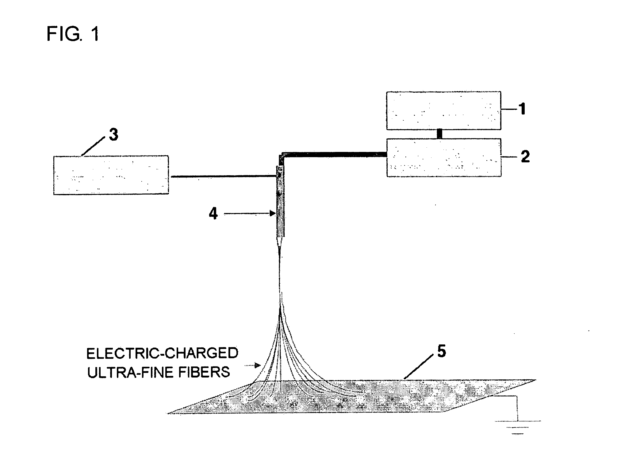
[0078] 20 g of PVdF (Kynar 761) was added to 100 g of dimethylacetamide / acetone mixture, and the resulting mixture was stirred at room temperature to give a clear polymeric solution. The resulting polymeric solution was introduced into a barrel of an electrospinning apparatus and then discharged onto a metal collector plate 5 at 100 μl / min with a constant quantity pump 2. At the same time, by applying 9 kV of electric charge to a spinning nozzle 4, an ultra-fine fibrous porous polymer membrane 6 of 50 μm in thickness was formed onto the earthed metal conveyer collector plate 5 that was moving at 1 m / min.

[0079] Next, as shown in FIG. 3, on the end portion of the conveyer, the collector plate, on which the fibrous polymer membrane was stacked, was adhered onto the surface of a cathode or an anode, heat-laminating process was performed with a roller 7 which was pre-heated at about 100° C., the electrode was then separated from the collector plate, to obtain a fibrous membrane / electrod...

example 1-2

[0081] 10 g of PVdF (Kynar 761) and 10 g of PAN (obtained from Polyscience Company, molecular weight of 150,000) were added into 100 g of dimethylacetamide, and the resulting mixture was stirred at room temperature for 24 hours to give a clear polymeric solution. Using the polymeric solution, a fibrous membrane / cathode composite in which an ultra-fine fibrous porous polymer membrane was combined with one side of LiCoO2 cathode and a fibrous membrane / anode composite in which an ultra-fine fibrous porous polymer membrane was combined with one side of graphite anode were respectively prepared in the same manner as in Example 1-1.

[0082] Using the same polymeric solution, a fibrous membrane / cathode composite in which an ultra-fine fibrous porous polymer membrane was combined with both sides of LiCoO2 cathode and a fibrous membrane / anode composite in which an ultra-fine fibrous porous polymer membrane was combined with both sides of graphite anode were respectively prepared in the same m...


PUM


Abstract

Disclosed are a lithium secondary battery comprising a fibrous membrane / electrode composite in which an ultra-fine fibrous porous polymer membrane is combined with an electrode into one body and a hybrid type polymer electrolyte in which pores of the ultra-fine fibrous porous polymer membrane is impregnated with an organic electrolyte solution or a polymer electrolyte; and a fabrication method thereof.

Description

BACKGROUND OF THE INVENTION [0001] 1. Field of the Invention [0002] The present invention relates to a lithium secondary battery comprising a ultra-fine fibrous porous polymer membrane and a fabrication method thereof. [0003] 2. Description of the Related Art [0004] Since electronic apparatus have become miniaturized and light-weighted, researches for developing energy sources having high density and energy have been intensively performed. A lithium secondary battery has been proposed as one energy source in view that the higher integration of energy is possible because molecular weight of lithium is very low while its density is relatively high. [0005] The early lithium secondary batteries were fabricated with metallic lithium or a lithium alloy as an anode. However, the cycle characteristic of the secondary battery using metallic lithium or a lithium alloy is low due to the dendrite formed on the anode as a result of repeated charging and discharging of the battery. [0006] A lithi...

Claims


Application Information

Patent Timeline
IPC IPC(8): H01M4/04H01M4/131H01M4/133H01M4/62H01M6/16H01M10/0525H01M10/0565H01M10/36H01M50/414H01M50/417H01M50/42H01M50/426H01M50/429
CPCH01M2/162H01M4/0473H01M4/131H01M4/133Y02E60/122H01M10/0525H01M10/0565H01M2300/004H01M2300/0085H01M4/621Y02E60/10H01M50/44Y02P70/50H01M50/417H01M50/429H01M50/414H01M50/426H01M50/42H01M10/058B82Y30/00
Inventor JO, SEONG MULEE, WHA SEOP
Owner SAMSHIN CREATION
Why Eureka
Try Eureka