Dye-sensitized solar cell

a solar cell, dye-sensitized technology, applied in the direction of non-aqueous electrolyte cells, electrochemical generators, electrolytic capacitors, etc., can solve the problems of difficult to quantify the concentration of iodine in the gel electrolyte, difficult to cause the gel electrolyte to penetrate into the pores, and difficult to achieve the effect of gel electrolyte penetration

Inactive Publication Date: 2005-04-14
SHARP KK +1
View PDF6 Cites 15 Cited by
  • Summary
  • Abstract
  • Description
  • Claims
  • Application Information

AI Technical Summary

Benefits of technology

The compound D can be a compound having an active hydrogen group. Such active hydrogen group is preferably one or more selected from a group of a carboxyl group, an amino group and a hydroxyl group.
At least either of the compounds A and D can be a compound having a polymer structure of a molecular weight of 500 to 20,000. Such polymer structure, either entirely or partially, is preferably one or more selected from a group of polyether, polyester, polycarbonate and polycaprolactone. Among these, the polyether structure can be, for example, represented by a following general formula (I)

Problems solved by technology

However, the above-mentioned JP-A No. 9-27352 describes a opto-electric device utilizing a polymer network of a polyether-type monomer, but is associated with a drawback that, since the monomer is crosslinked by a radical polymerization, the polymerization is hindered in case iodine employed in the dye-sensitized solar cell is present in the monomer prior to the crosslinking.
It is also difficult to quantify an iodine concentration in the gel electrolyte, since iodine is introduced after the polymerization.
Also in a dye-sensitized solar cell, since the porous semiconductor layer is formed with particles of a size in the order of a nanometer, it is more difficult to cause the gel electrolyte to penetrate into pores than in a lithium secondary battery which employs an electrode material of a size in the order of a micrometer.
For this reason, the technology disclosed in JP-A No. 7-320782 is difficult to apply to a dye-sensitized solar cell.
2000-15006, being based on polyalkylene oxide of a relatively high molecular weight, it is difficult for the gel electrolyte to penetrate into the pores even if using a solvent for dilution and it is troublesome that the solvent has to be eliminated.

Method used


Image

  • Dye-sensitized solar cell
  • Dye-sensitized solar cell
  • Dye-sensitized solar cell

Examples


example 1-1

A dye-sensitized solar cell utilizing a polymer solid electrolyte was prepared in a following method, and a conversion efficiency thereof was evaluated.

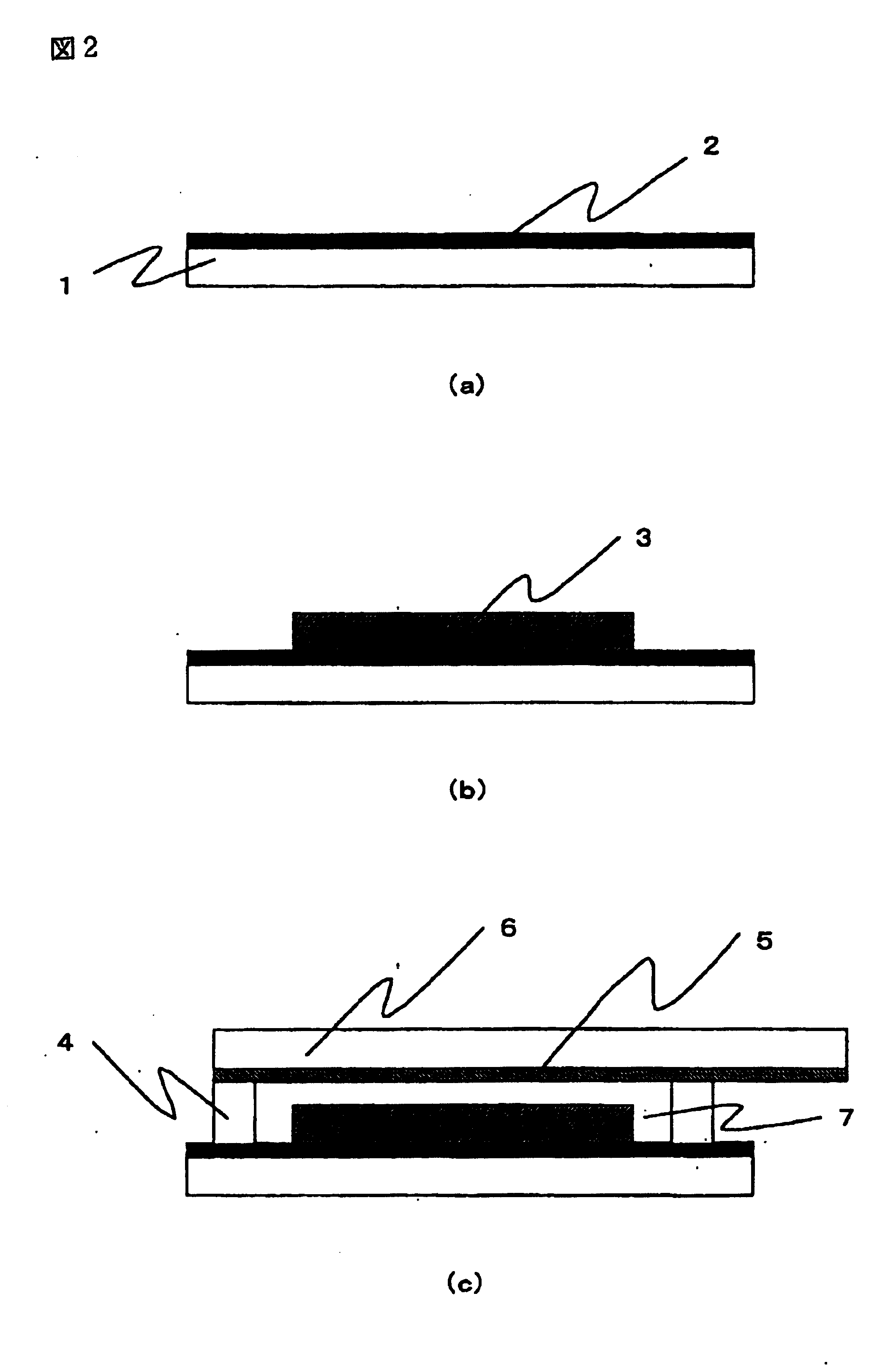
A preparation process for the dye-sensitized solar cell will be explained with reference to FIG. 2. In FIG. 2, (a) to. (c) are schematic cross-sectional views of a dye-sensitized solar cell, following preparation steps thereof. In FIG. 2, there are shown a transparent substrate 1, a transparent conductive film 2, a titanium oxide film 3, a separator 4, a platinum film 5, a conductive substrate 6, and a gel electrolyte layer 7.

On a transparent substrate 1 formed by a glass, a transparent conductive film 2 of SnO2 was formed by vacuum evaporation, and a titanium oxide film 3 was formed on the transparent conductive film 2 by a following method.

As a titanium oxide suspension for forming the titanium oxide film 3, there was employed a commercially available titanium oxide suspension (manufactured by Solaronix Inc., trade name: Ti-...

example 1-2

There were employed 1.3 g of trimethylolpropane-denatured tolylene diisocyanate (manufactured by Nippon Polyurethane Industry Co., trade name: Coronate L) as the compound A, 10 g of polyetheramine (manufactured by Huntsman Corp., trade name: Jeffamine T-5000) as the compound B, and 101.7 g of the liquid electrolyte.

example 1-3

There were employed 4.2 g of a compound obtained by a following synthesis method 1-2 as the compound A, 2 g of polyetheramine (manufactured by Huntsman Corp., trade name: Jeffamine T-5000) as the compound B, and 200 g of the liquid electrolyte.

(Synthesis Method 1-2)

In a reaction vessel, there were charged 92 g of glycerin as a starting material and 30 g of potassium hydroxide as a catalyst. There were also charged 5,950 g of ethylene oxide and 3,970 g of propylene oxide, and after a reaction for 10 hours at 130° C., a neutralization-dehydration process was executed to obtain an ethylene oxide-propylene oxide copolymer of a molecular weight of 10,000. To 100 g of the obtained compound, 5.3 g of tolylene diisocyanate and 0.05 g of dibutyl tin dilaurate as a catalyst were added and reacted for 3 hours at 80° C. to obtain a compound of a molecular weight of 10,520.


PUM

PropertyMeasurementUnit
transparentaaaaaaaaaa
transparent conductiveaaaaaaaaaa
conductiveaaaaaaaaaa

Abstract

The invention provides a dye-sensitized solar cell including a transparent substrate, a transparent conductive film formed on a surface thereof, and a conductive substrate provided in a position opposed to the transparent conductive film, and further having a porous semiconductor layer, in which a dye is adsorbed, and an electrolyte between the transparent conductive film and the conductive substrate, wherein the electrolyte is a gel electrolyte containing a redox material and a solvent capable of dissolving the same in a network structure formed by crosslinking at least one kind of compound A including an isocyanate group and at least one kind of compound B including an amino group. Otherwise, the electrolyte is a gel electrolyte containing a redox material and a solvent capable of dissolving the same in a network structure formed by crosslinking at least one kind of compound A including an isocyanate group and at least one kind of compound C including a carboxyl group and/or a hydroxyl group. Otherwise, the electrolyte is a polymer solid electrolyte containing redox material in a network structure formed by crosslinking at least one kind of compound A including an isocyanate group and at least one kind of compound D reactive with the isocyanate group. The configuration of the invention facilitates an electrolyte composition of the dye-sensitized solar cell, and simplifies process steps in the manufacture.

Description

TECHNICAL FIELD The present invention relates to a dye-sensitized solar cell, and more particularly to a dye-sensitized solar cell employing a gel electrolyte containing a redox material and a solvent capable of dissolving the same in a network structure formed by crosslinking a compound having a specified structure, or a dye-sensitized solar cell employing a polymer solid electrolyte containing a redox material in a network structure formed by crosslinking a compound having a specified structure. BACKGROUND ART The dye-sensitized solar cell is attracting attention widely because of a higher conversion efficiency among organic solar cells. As a semiconductor layer formed by a photoelectric converting material employed in such dye-sensitized solar cell, there is employed a semiconductor in which a spectral sensitizing dye having an absorption in the visible region is surfacially adsorbed. For example Japanese Patent No. 2664194 describes a dye-sensitized solar cell employing a met...

Claims


Application Information

Patent Timeline
Patent Type & Authority Applications(United States)
IPC IPC(8): H01G9/20H01M6/18H01L31/04H01M14/00
CPCH01G9/2009H01G9/2031Y02E10/542H01M14/005H01M6/181
Inventor KOMIYA, RYOICHIHAN, LIYUANYAMANAKA, RYOHSUKEISHIKO, ERIKOKONO, MICHIYUKI
Owner SHARP KK
Why Eureka
Try Eureka