Tidal vertical flow wastewater treatment system and method

US20050082222A1Inactive Publication Date: 2005-04-21DHARMA IP

Image

  • Tidal vertical flow wastewater treatment system and method
  • Tidal vertical flow wastewater treatment system and method
  • Tidal vertical flow wastewater treatment system and method

Examples


Embodiment Construction

[0029] A description of the preferred embodiments of the present invention will now be presented with reference to FIGS. 1-3.

System Elements

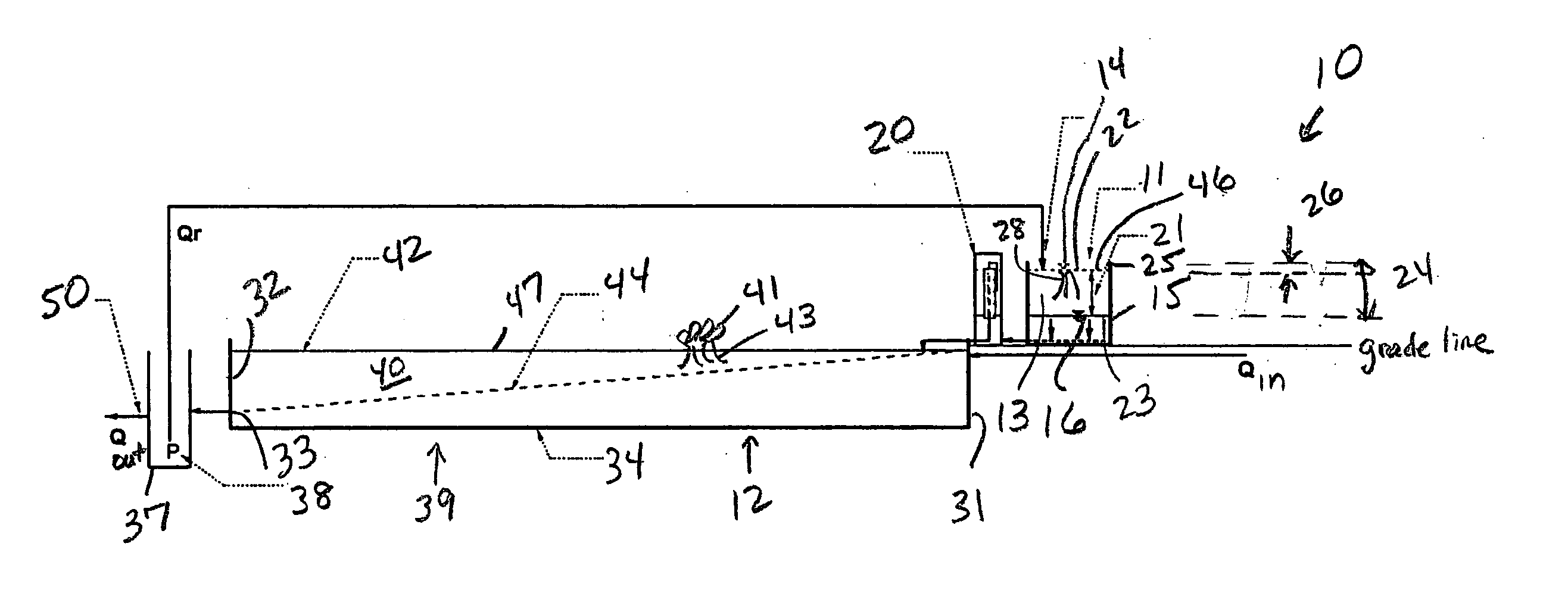
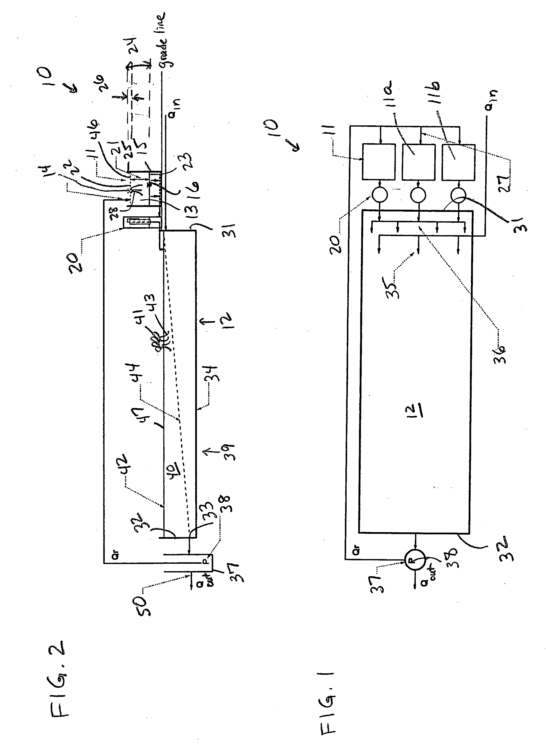
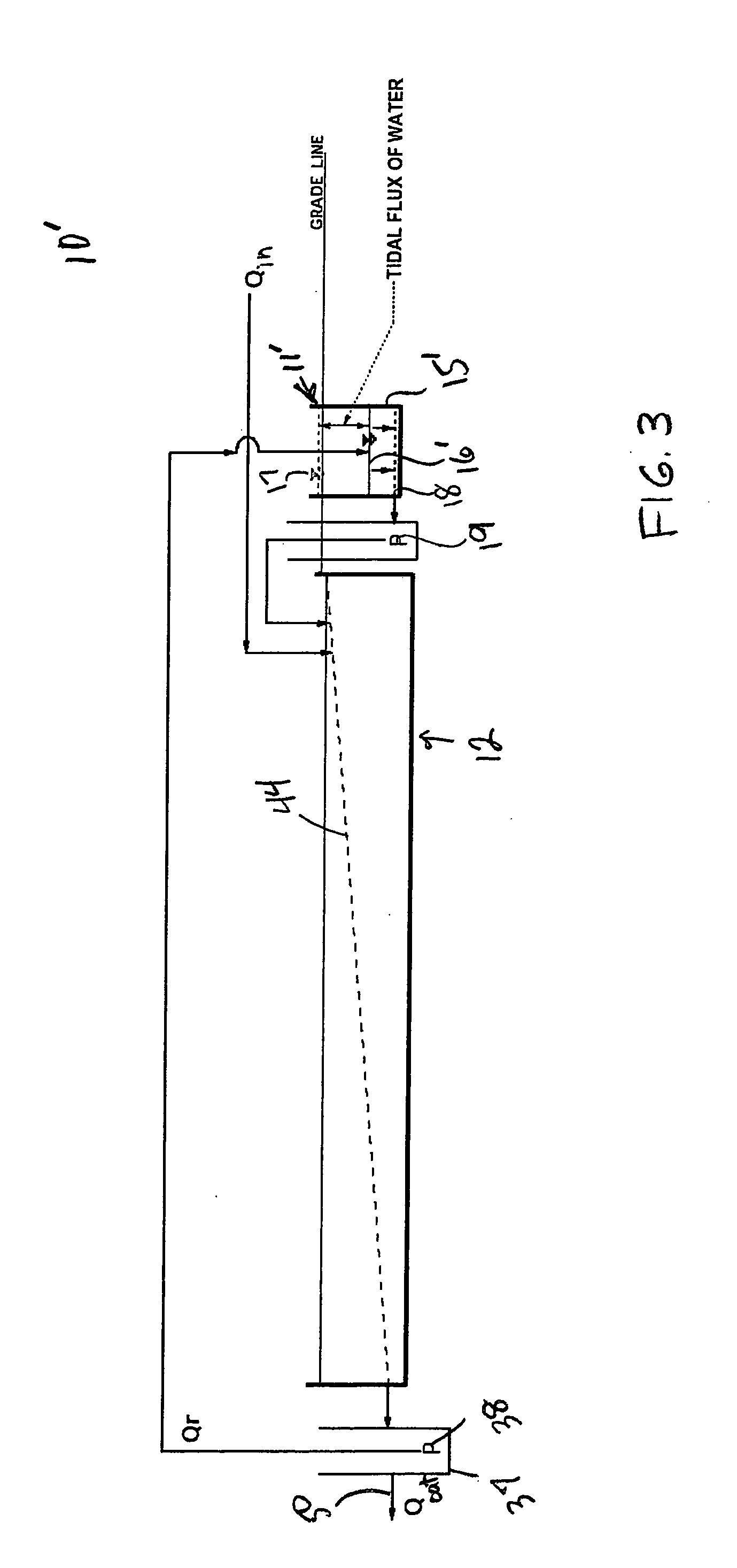
[0030] A preferred embodiment of the present invention comprises a system 10 that includes a vertical flow marsh cell 11 in fluid communication with a subsurface horizontal flow wetland 12. The system 10 may be installed as depicted, or the marsh cell 11 and associated components may be added to an existing wetland 12 (“retrofit”) to improve the performance thereof. Preferably, depending upon the site characteristics, the system 10 may comprise a plurality of marsh cells 11 shown here as three marsh cells 11, 11a, 11b, configured in parallel, although this is not intended as a limitation. As these are substantially identical, only one marsh cell 11 will be described herein. In another embodiment (FIG. 3), a below-ground system 10′ with a marsh cell 11′ is depicted.

[0031] In a preferred embodiment, the marsh cell 11 comprises a substantially ...


PUM

PropertyMeasurementUnit
Timeaaaaaaaaaa
Diameteraaaaaaaaaa
Diameteraaaaaaaaaa

Abstract

A wastewater treatment system includes a vertical flow marsh cell that is adapted to contain media and to support plants having roots extending into the media, the roots and media positioned to contact water flowing downward through the marsh cell during a flooding stage, the media and plant roots providing surfaces to which biofilms can adsorb, the biofilms containing bacteria adapted to adsorb ammonium ions and nitrify ammonium ions to nitrate during an aerated drained phase. The marsh cell is configured to receive water from an outlet of a horizontal wetland that functions essentially anaerobically / anoxically to contain bacteria for transforming nitrate into nitrogen gas. Water to be treated and water exiting the marsh cell outlet are transportable to a wetland inlet, providing dilution of incoming wastewater. Treated water is discharged from the wetland outlet.

Description

BACKGROUND OF THE INVENTION [0001] 1. Field of the Invention [0002] The present invention relates generally to wastewater treatment systems and methods, and, more particularly, to such systems and methods using bioremediation techniques. [0003] 2. Related Art [0004] Engineered wetlands for wastewater treatment are known to have three basic hydraulic configurations: surface flow (SF), subsurface horizontal flow (SSHF), and vertical flow (VF). The first two are believed the most common, and are known to have significant design shortcomings. Even though an early wastewater treatment wetland design utilized vertical flow, design criteria are still considered experimental for vertical flow wetlands. Surface-loaded, vertical-flow wetlands are believed advantageous because surface loading forces flow through the root zone. [0005] The basic hydraulic flow path for VF wetlands is for wastewater to be introduced at the wetland surface, pass through media and plant roots, then to flow out of t...

Claims


Application Information

Patent Timeline
21 Apr 2005
Publication
US20050082222A1
IPC
C02F3/30; C02F3/32
CPC
C02F3/302; C02F2103/001; C02F3/327; Y02W10/10
Inventors
AUSTIN, DAVID C.