

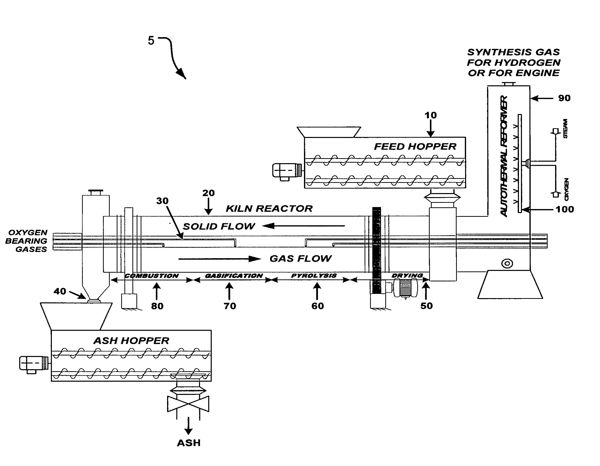
Process and apparatus for biomass gasification
a biomass gasification and process technology, applied in the direction of gasifier mechanical details, combustible gas catalytic treatment, combustible gas production, etc., can solve the problems of unsolved problems in the industry, increased energy required to preheat and vaporize water content, and carbon imbalance at the earth's surfa
- Summary
- Abstract
- Description
- Claims
- Application Information
AI Technical Summary
Problems solved by technology
Method used
Image

Examples
example 1
[0058] On a dry basis by weight, cellulosic type compounds compose about 62% of wood, 43% of bagasse and 35% of rice husk. When these compounds undergo pyrolysis, the following chemical reaction takes place: (C6H10O5)nCellulosic Cqd.+Heat⟶C6H8OPyrolysis Oil+CCharcoal+H2OSteam+H2Hydrogen+CH4Methane+C2H4Ethylene+COCarbon Monoxide+CO2Carbon Dioxide+RCOOHAcids+ROHAlcohols+Tars(9)
where R can be H, CH3, C2H5 or C3H7.
[0059] Only a limited amount of the oxygen supplied (partial oxidation) may be used to generate heat for the endothermic gasification reactions. For example, during gasification, the complex structure of CnHmOp produced by pyrolysis may be reduced to a simpler gaseous component, as seen in reaction (2) above. Further, char produced by pyrolysis may be combusted within the gasifier to produce process heat, as seen in reaction (3) above. No solids recycling may be needed within the gasifier.
[0060] Through the selection of particular operating conditions, variou...
example 2
[0061] For gasification of cellulosic type compounds such as C6H10O5 (i.e. n=6, m=10, p=5) with an equivalence ratio of 0.167 i.e. χ=1 in equation (3), the gasification reaction with heat can be represented as follows:
C6H10O5+O2+(12−2−5)H2O→(6−y)CO2+(12−2−5+5−y)H2+yCO+yH2O (10)
or
C6H10O5+O2+5H2O→(6−y)CO2+(10−y)H2+yCO+yH2O (11)
when y=0
C6H10O5+O2+5H2O→6CO2+10H2 (12)
when y=3
C6H10O5+O2+2H2O→3CO2+7H2+3CO (13)
when y=5
C6H10O5+O2→CO2+5H2+5CO (14)
when y=6
C6H10O5+O2→4H2+6CO+H2O (15)
[0062] When χ equals 1 (or the equivalence ratio equals 0.167), the product gas from C6H10O5 due to the gasification step alone will have a composition of:
TABLE 3PRODUCT GAS COMPOSITION FROM GASIFICATION OFCELLULOSIC TYPE COMPOUNDSMOL %, DRY, χ = 1PRODUCT GASy = Oy = 5y = 6H262.545.536.4CO—45.554.5CO237.59.0—TOTAL100.0100.0100.0
example 3
[0063] In general, biomass has lower heating values than fossil fuels such as bituminous coal, oil or natural gas. It is beneficial to extend the range of compatible feedstocks such as municipal solid waste, used tires, waste oils, etc. In this example, a waste oil (CH11.4H2.8) is fed together with the biomass to the two-stage gasifier. The gasification with heat of the waste oil, i.e. n=11.4, m=22.8, p=0, with oxygen and steam with an equivalence ratio of 0.25, i.e. χ32 5.7, the following equations may apply:
C11.4H22.8+5.7O2+11.4H2O→11.4CO2+22.8H2 (when y=0) (16)
C11.4H22.8+5.7O2+5.7H2O→5.7CO2+17.1H2+5.7CO (when y=5.7) (17)
C11.4H22.8+5.7O2→11.4H2+11.4CO (when y=11.4) (18)
[0064] The product gas from the gasification of waste oil may have a composition according to Table 4 below:
TABLE 4PRODUCT GAS COMPOSITION FROMGASIFICATION OF WASTE OILSMol %, dryProduct Gasy = 0y = 5.7y = 11.4H266.760.050.0CO—20.050.0CO233.320.0—TOTAL100.0100.0100.0
[0065] Both the carbon steam and reverse ...
PUM
| Property | Measurement | Unit |
|---|---|---|
| Flow rate | aaaaa | aaaaa |
| Ratio | aaaaa | aaaaa |
Abstract
Description
Claims
Application Information