Source gas flow control and CVD using same

a flow control and source gas technology, applied in the direction of machines/engines, combustible gas purification/modification, and test/measurement of semiconductor/solid-state devices, etc., can solve the problem of insufficient supply pressure, malfunction of flow control valves, and flow errors of thermal type flowmeters disposed inside the flow controllers, etc. problems, to achieve the effect of excellent reproducibility

Inactive Publication Date: 2005-05-12
ADVANCED ENERGY JAPAN +1
View PDF15 Cites 40 Cited by
  • Summary
  • Abstract
  • Description
  • Claims
  • Application Information

AI Technical Summary

Benefits of technology

[0049] Furthermore, in at least one embodiment of the present invention, reproducibility of a film thickness at the time of consecutive film formation on 1000 pieces of substrates can be ±0.99%; and excellent reproducibility can be achieved.

Problems solved by technology

If conventional gasifiers and gas mass flowmeters are used, the following problems occur.
The first problem is that supply pressure becomes insufficient due to vapor pressure drop.
Even with a flow controller having a heating device, a pressure of the reaction gas being supplied to the flow controller drops by latent heat generated by gasification of the liquid source material with the start of supplying the reaction gas, causing malfunction of a flow control valve or a flow error of a thermal type flowmeter disposed inside the flow controller due to pressure change of the reaction gas.
Because thermal type flowmeters detect a flow rate of a gas running inside them from heat conduction of the gas, changes are detected as flow rate errors if gas pressure changes and heat capacity is changed.
This boiling causes an uncontrollable change in a pressure of a gas taken out, blocking stable flow rate control by a mass flow controller.
This unstable flow rate control and a flow rate with an error cause serious problems in film formation onto a semiconductor substrate.
If a flow rate of the reaction gas is deviated from a design value, a thickness and quality of a thin film formed are deviated from design values, causing malfunction of LSI devices.
Additionally, if flow rate control becomes unstable, plasma discharge becomes unstable, forming an uneven film or generating abnormally discharge.
The second problem is that a more serious uncontrollable flow rate situation occurs if a direct gasifier which gasifies a liquid directly is used.
Alkoxysilicon or alkylsilicon compounds have high vapor pressure and their boiling points are in the range of 20-100° C. In a direct gasification method, because a liquid is forcibly gasified by directly heating it by a flow control valve, the liquid is gasified in portions having high temperature in addition to a gasification portion for which a flow rate is controlled; gas generated in the portions other than the gasification portion causes rapid pressure fluctuations to the flow control valve, hindering stable gasification and flow rate control.
If gasification / flow rate control is executed in this state, the gasified reaction gas with pulsation is fed from the gasified gas flow controller to the reaction chamber, creating unstable gas concentration in a film formation area in which a semiconductor substrate is placed.
This unstable gas concentration causes plasma discharge blinking or arc discharge, generating particles in a reaction space or abnormal film growth.

Method used


Image

  • Source gas flow control and CVD using same
  • Source gas flow control and CVD using same
  • Source gas flow control and CVD using same

Examples


example 1

Nitrogen-Containing Silicon Carbide Film

[0091] Film Formation Conditions: [0092] Si(CH3)4=250 sccm, NH3=250 sccm, He=2500 sccm, pressure 600 Pa, substrate temperature=385° C., 1st RF power 27.12 MHz at 600 W, 2nd RF power 400 kHz at 70 W, electrode spacing=20 mm

[0093] Film Characteristic Measurement Results: [0094] Growth rate=100 nm / min., dielectric constant=4.55 (by a mercury probe), film-thickness non-uniformity =±1.8%, refractive index=1.99, film compressive stress=250 MPa, leakage current=5×10⁻⁹ A / cm2 (2MV / cm)

example 2

Nitrogen-Containing Silicon Carbide Film

[0095] Film Formation Conditions: [0096] Si(CH3)4=220 sccm, NH3=250 sccm, He=2600 sccm, pressure 665 Pa, substrate temperature=385° C., 1st RF power 27.12 MHz at 575 W, 2nd RF power 400 kHz at 70 W, electrode spacing=20 mm

[0097] Film Characteristic Measurement Results: [0098] Growth rate=100 nm / min., dielectric constant=4.40 (by a mercury probe), film-thickness non-uniformity =±1.6%, refractive index=1.90, film compressive stress=200 MPa, leakage current=2×10⁻⁹ A / cm2 (2MV / cm)

example 3

Oxygen-Containing Silicon Carbide Film

[0099] Film Formation Conditions: [0100] Si(CH3)4=300 sccm, CO2=1900 sccm, He=2500 sccm, pressure 533 Pa, substrate temperature=385° C., 1st RF power 27.12 MHz at 450 W, 2nd RF power 400 kHz at 90 W, electrode spacing=20 mm

[0101] Film Characteristic Measurement Results: [0102] Growth rate=200 nm / min., dielectric constant=4.30 (by a mercury probe), film-thickness non-uniformity =±1.2%, refractive index=2.05, film compressive stress=240 MPa, leakage current=5×10⁻⁸ A / cm2 (2MV / cm)

[0103] B) Examples Using Dimethyldimethoxysilane (DMDMOS) as a Source Gas


PUM

PropertyMeasurementUnit
boiling pointaaaaaaaaaa
dielectric constantsaaaaaaaaaa
boiling pointaaaaaaaaaa

Abstract

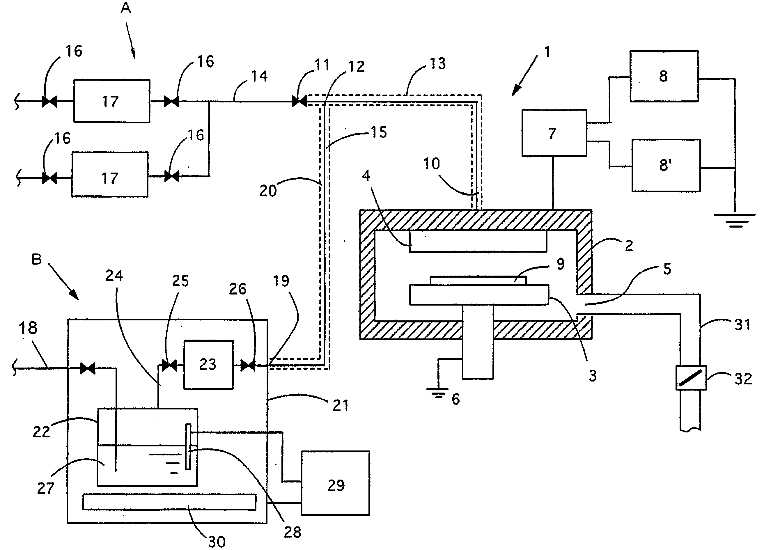
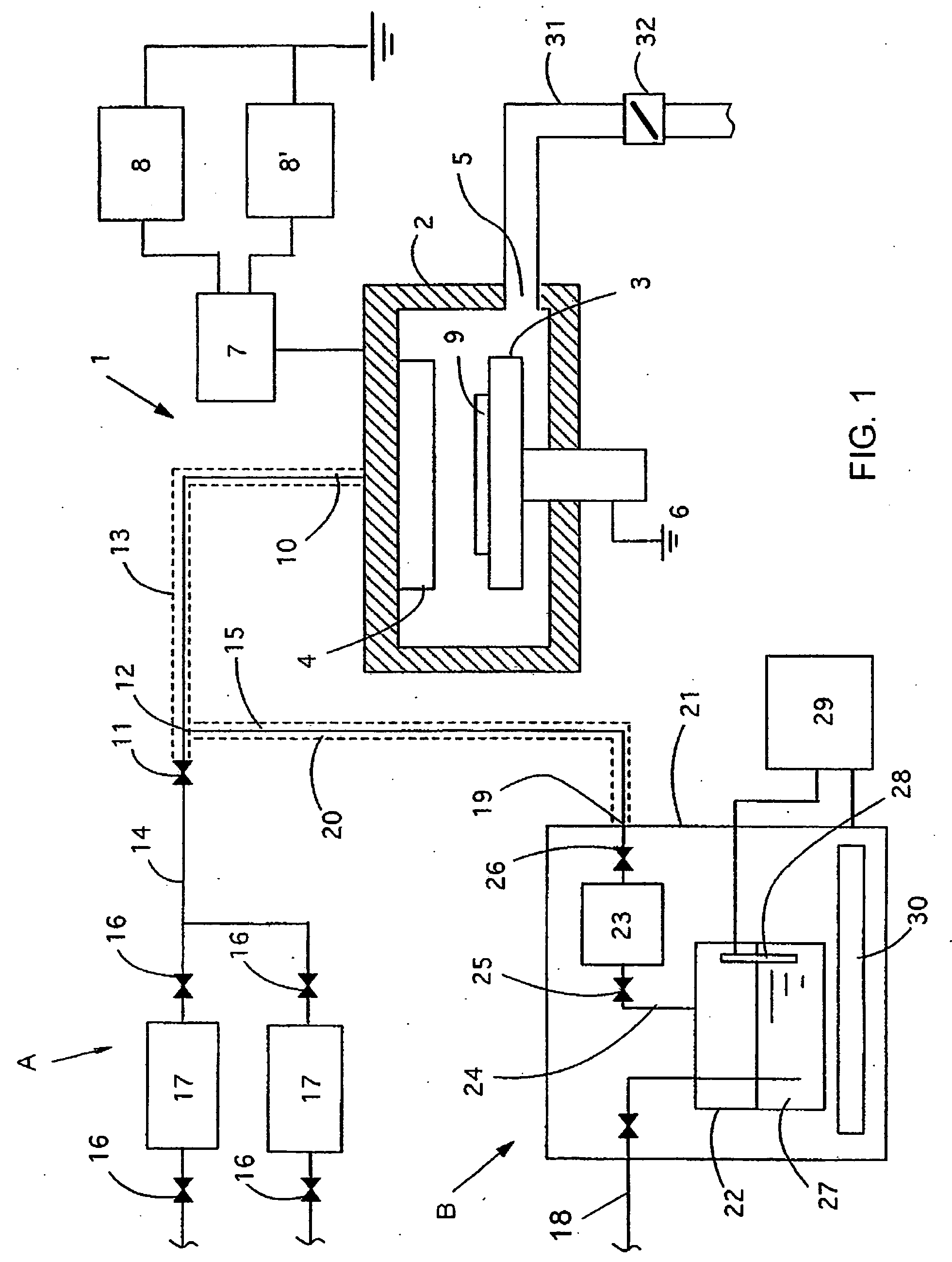
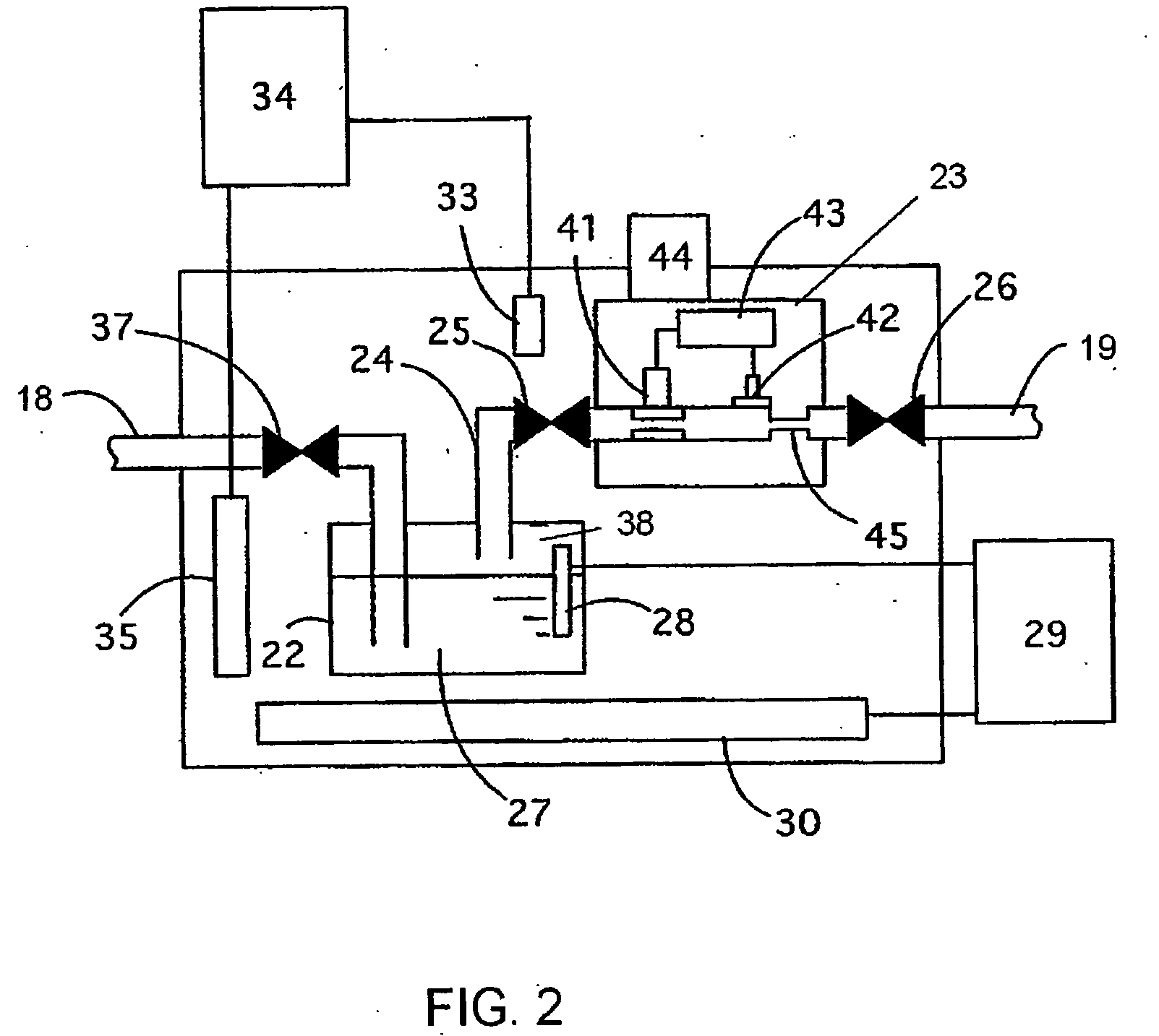
A source-gas supply apparatus for supplying a source gas into a CVD reactor includes: a reservoir for storing a liquid material; a gas flow path connected the reservoir and the CVD reactor; a sonic nozzle disposed in the gas flow path, through which the source gas is introduced into the CVD reactor; a pressure sensor disposed in the gas flow path upstream of the sonic nozzle; a flow control valve disposed in the gas flow path upstream of the pressure sensor; and a flow control circuit which receives a signal from the pressure sensor and outputs a signal to the flow control valve to adjust opening of the flow control valve as a function of the signal from the pressure sensor.

Description

BACKGROUND OF THE INVENTION [0001] 1. Field of the Invention [0002] The present invention generally relates to a plasma CVD apparatus for forming a thin film on a semiconductor substrate or a glass substrate; and particularly to an apparatus for supplying a reaction gas gasified from a liquid material used for film formation. [0003] 2. Description of the Related Art [0004] In recent years, copper having smaller electric resistance has been adopted as a metal wiring material in order to make LSI devices faster, and carbon-containing silicon oxide films having low dielectric constants have been adopted as insulation films between lines in order to reduce capacitance between lines, which causes signal delays. In a method for forming these carbon-containing silicon oxide films, an alkoxysilicon compound having a silane structure is used as a source material in order to form films having a given structure: In the above, the term “carbon-containing silicon oxide films” used herein is used...

Claims


Application Information

Patent Timeline
Patent Type & Authority Applications(United States)
IPC IPC(8): C23C16/36C23C16/40C23C16/455H01L21/205C23C16/448
CPCC23C16/36C23C16/455C23C16/401
Inventor SATOH, KIYOSHILEE, HAK JUNISHIKAWA, TOMOHISASASAKI, AKIRANANBU, MASAHIRO
Owner ADVANCED ENERGY JAPAN
Why Eureka
Try Eureka