Miniaturized multi-gas and vapor sensor devices and associated methods of fabrication

a sensor device and nano-scale technology, applied in the direction of instruments, material heat development, specific gravity measurement, etc., can solve the problems of limited materials that may be used to build devices, none of these devices demonstrate the desired combination of robustness, sensitivity, repeatability, and reliability, and it is difficult to optimize with conventional multi-gas and vapor sensor devices without making sacrifices with respect to other performance parameters. , high sensitivity of differential scanning nano, high adsorption ra

Inactive Publication Date: 2005-05-26
GENERAL ELECTRIC CO
View PDF7 Cites 62 Cited by
  • Summary
  • Abstract
  • Description
  • Claims
  • Application Information

AI Technical Summary

Benefits of technology

[0005] In various embodiments, the invention provides robust, high-sensitivity, high-selectivity, high-stability multi-gas and vapor sensor devices and platforms, among other sensor devices and platforms, and associated methods of fabrication. The multi-gas and vapor sensor devices exploit the high sensitivity of differential scanning nano and picocalorimetry microelectromechanical systems (MEMS) to heat flow and the unique properties of certain thin films and nano and picoparticles, such as zeolite thin films and nano and picoparticles, a

Problems solved by technology

The wide range of environments to which these devices may be exposed severely limits the candidate materials that may be used to build the devices.
However, none of these devices demonstrate a suitable combination of the desired robustness, sensitivity, selectivity, stability, size, simplicity, reproducibility, reliability, response time, resistance to contaminants, and longevity.
Response time and sensitivity are critical in many sensing applications, such as in sensing for warfare agents, measuring low dew points, detecting trace gases, etc., but are difficult to optimize with conventional multi-gas and vapor sensor devices without making sacrifices with respect to

Method used


Image

  • Miniaturized multi-gas and vapor sensor devices and associated methods of fabrication
  • Miniaturized multi-gas and vapor sensor devices and associated methods of fabrication
  • Miniaturized multi-gas and vapor sensor devices and associated methods of fabrication

Examples


Embodiment Construction

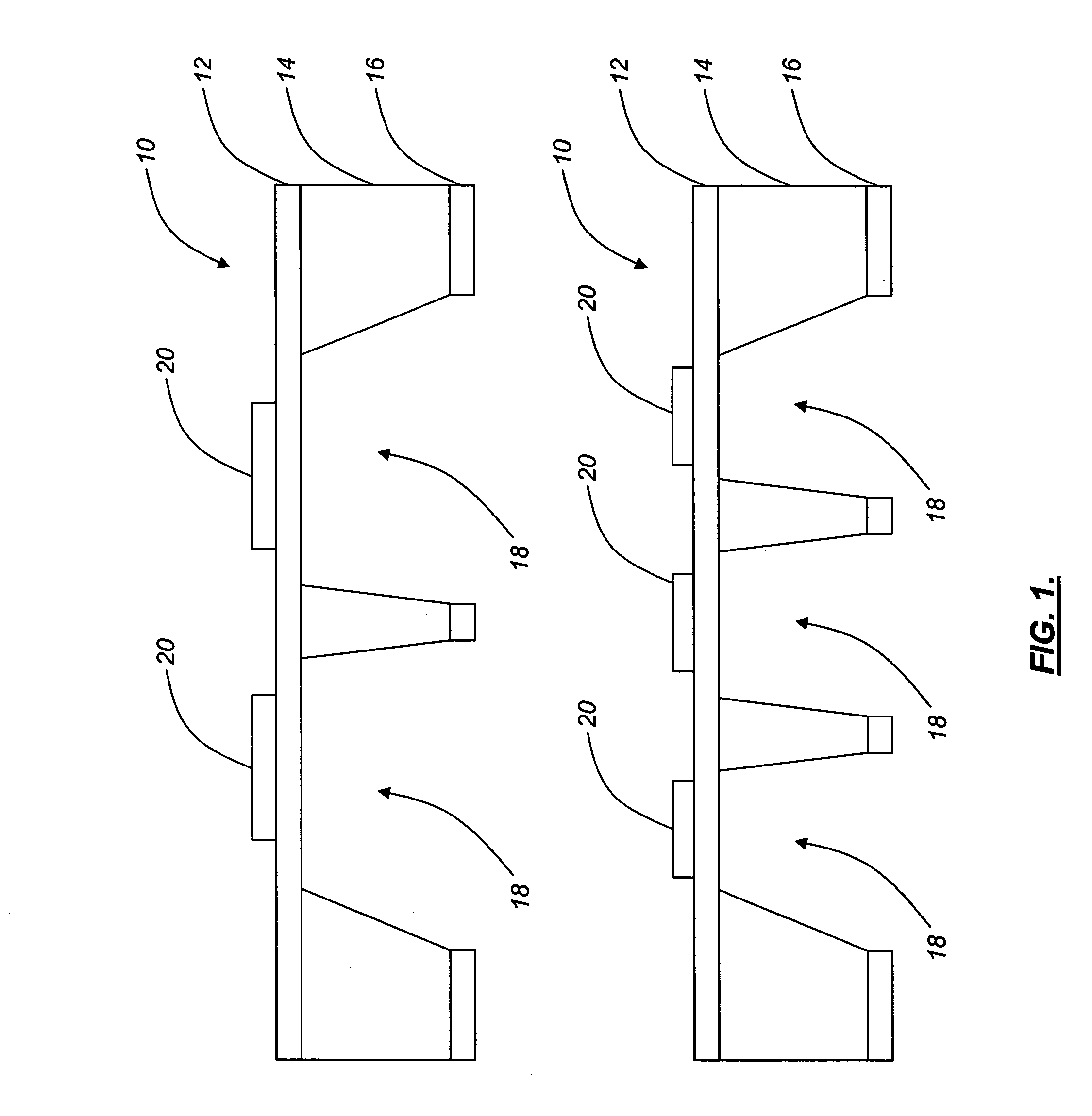
[0039] Referring to FIG. 1, the sensor device 10 of the invention, which may be a multi-gas or vapor (e.g., humidity) sensor device, among other sensor devices, consists of a multi-cell ultra high-sensitivity differential scanning calorimeter (UHSDSC), which is a microelectromechanical system (MEMS). The sensor device 10 is fabricated using standard silicon processing techniques, well known to those of ordinary skill in the art. The sensor device 10 includes a thin, thermally-insulating silicon oxinitride (SiONx) membrane 12 disposed directly adjacent to a silicon (Si) frame 14. It should be noted that other suitable materials may replace the silicon oxinitride membrane 12 and / or the silicon frame 14. For example, the silicon oxinitride membrane 12 may be replaced with a silicon, polysilicon, parylene, or polyimide membrane. Preferably, a thin silicon oxinitride layer 16 is also disposed directly adjacent to the silicon frame 14 opposite the silicon oxinitride membrane 12. Again, ot...


PUM


Abstract

The invention provides a miniaturized sensor device including a thin film membrane having a first surface and a second surface, one or more resistive thin film heater/thermometer devices disposed directly or indirectly adjacent to the first surface of the thin film membrane, and a frame disposed directly or indirectly adjacent to the second surface of the thin film membrane, wherein one or more internal surfaces of the frame define at least one cell having at least one opening. The sensor device also includes a thin film layer disposed directly or indirectly adjacent to the frame. The sensor device further includes a sensing layer disposed directly or indirectly adjacent to the thin film membrane.

Description

FIELD OF THE INVENTION [0001] The invention relates generally to the field of miniaturized sensor devices and platforms and, more specifically, to the field of nano and pico-scale sensor devices and platforms. An aspect of the invention provides robust, high-sensitivity, high-selectivity, high-stability multi-gas and vapor sensor devices, among other sensor devices, and associated methods of fabrication. Variants of the multi-gas and vapor sensor devices of the invention may be used for the in situ measurement of soluble analytes in liquid media. Another aspect of the invention provides a thermally-isolated micro-platform for such microelectromechanical systems (MEMS). A further aspect of the invention provides a design for wide-dynamic range, micro-machined humidity sensor devices, among other sensor devices, that relieves the generated stresses in the associated sensing films caused by sensing film swelling due to the adsorption of water. A still further aspect of the invention pr...

Claims


Application Information

Patent Timeline
IPC IPC(8): G01N25/48
CPCB82Y15/00G01N25/4873G01N25/4813B82Y30/00
Inventor ZRIBI, ANISTIAN, WEI-CHENGSCHULTZ, GERALDKNOBLOCH, AARON JAY
Owner GENERAL ELECTRIC CO
Why Eureka
Try Eureka