

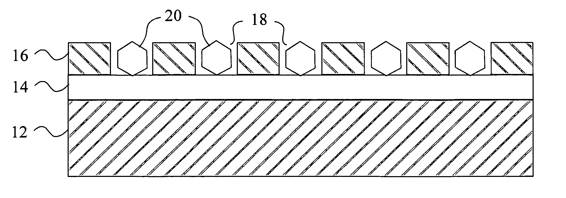
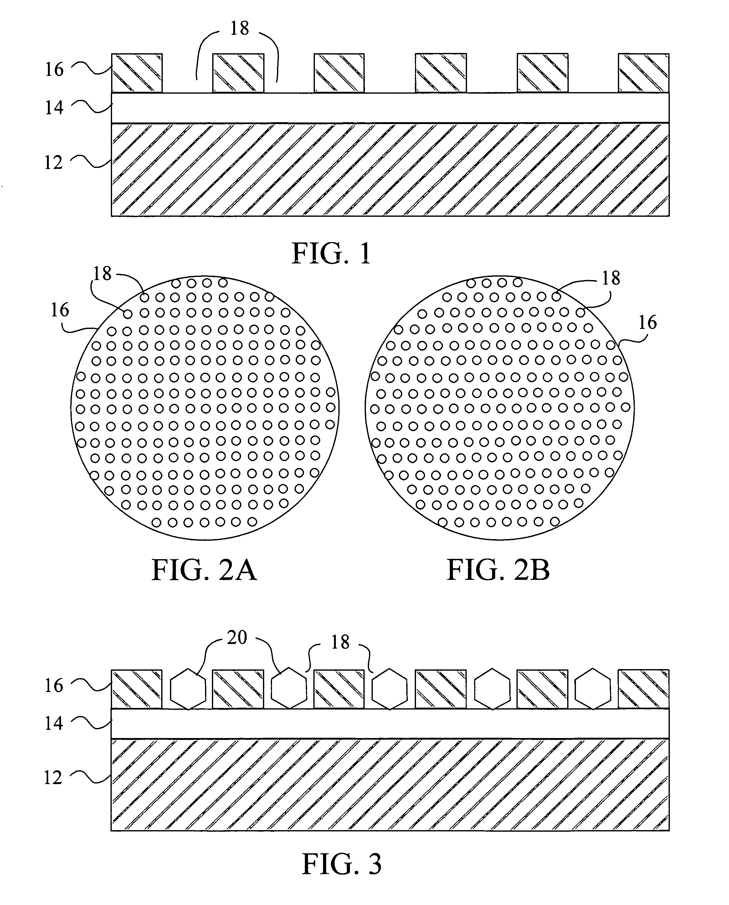
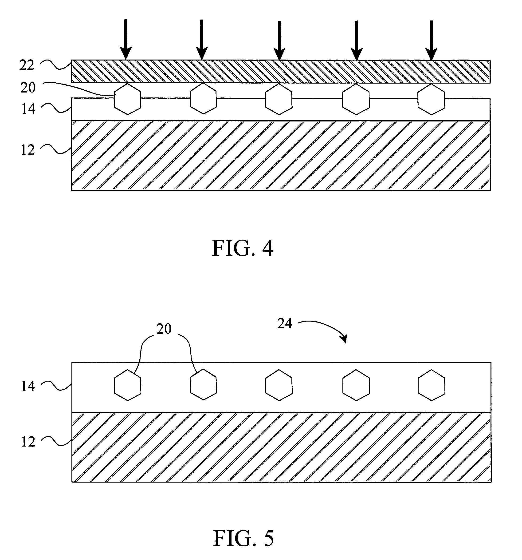
Superabrasive particle synthesis with controlled placement of crystalline seeds
a superabrasive particle and seed technology, applied in metal sawing tool making, other chemical processes, grinding devices, etc., can solve the problems of affecting the thermal stability of diamond grit, requiring a much longer growth time, and diamonds with a lower amount of inclusions
- Summary
- Abstract
- Description
- Claims
- Application Information
AI Technical Summary
Benefits of technology
Problems solved by technology
Method used
Image

Examples
example 1
[0144] A circular mold having a diameter of 28 mm was filled with powdered natural graphite having an average size of about 20 μm, low resistivity of about 5 μΩ-cm, and a degree of graphitization of 0.8. The graphite was purified to be substantially free of oil, organic binders, ash, or other non-carbon materials. The graphite was cold pressed at 150 MPa to form a particulate compact disk having a thickness of 0.7 mm and a density of 2 g / cm3 (12% porosity). High purity INVAR (Fe-35Ni with a mesh size of less than 40 μm) was placed on top of the graphite layer and cold pressed at 300 MPa to form a particulate catalyst layer having a thickness of 0.2 mm and a density of 6 g / cm3 (about 20% porosity). A thin layer of adhesive was sprayed onto the particulate catalyst layer. A template similar to that shown in FIG. 2B, having apertures spaced 0.8 mm apart (center-to-center) and apertures 130 μm in diameter was placed on the catalyst layer. The template was covered in uncoated diamond see...
example 2
[0145] A circular mold having a diameter of 28 mm was filled with powdered natural graphite having an average size of about 20 μm, low resistivity of about 5 μΩ-cm, and a degree of graphitization of 0.8. The graphite was purified to be substantially free of oil, organic binders, ash, or other noit-carbon materials. The graphite was mixed with high purity INVAR (Fe-35Ni with a mesh size of less than 40 Sm). The weight ratio of graphite to metal catalyst was 1:1.5. The mixture was then cold pressed at 250 MPa to form a particulate compact disk having a thickness of 0.7 mm and a density of 2 g / cm3 (12% porosity). The particulate compact disk was coated with a thin layer of adhesive. A template similar to that shown in FIG. 2B, having apertures spaced 0.8 mm apart (center-to-center) and apertures 130 μm in diameter was placed on the compact disk. The template was covered in uncoated diamond seeds having a mesh size of 120 / 140 (about 115 μm in diameter) such that the apertures were fille...
example 3
[0146] Graphite disks were prepared by pressing natural graphite powder having a grain size of about 20 microns into disks 37 mm in diameter and 0.8 mm in thickness at about 400 MPa. The porosity of the resulting graphite disks was about 15%. Ni coated diamond seeds (precoated diameter of about 65-75 microns) having a coated diameter of about 105-125 microns were planted into the graphite disks in a grid pattern having a pitch of about 0.8 mm to form seeded graphite disks. The seeded graphite disks were alternated with INVAR (Fe65-Ni35) disks and loaded into a steel container to make a final growth cc I of 38.8 mm in diameter and 30 mm in height. One hundred of these growth cells were pressed in a 2500 ton cubic press with a ram size of 600 mm to attain a pressure of about 5.2 GPa and temperature of about 1250° C. The pressure and temperature were maintained for 50 minutes and then the pressure was reduced and the temperature gradually decreased. The pressed growth cells were broken...
PUM
| Property | Measurement | Unit |
|---|---|---|
| distance | aaaaa | aaaaa |
| particle size | aaaaa | aaaaa |
| size | aaaaa | aaaaa |
Abstract
Description
Claims
Application Information