Electrode for dielectrophoretic apparatus, dielectrophoretic apparatus, method for manufacturing the same, and method for separating substances using the electrode or dielectrophoretic apparatus

a technology of dielectrophoretic apparatus and dielectrophoretic apparatus, which is applied in the direction of liquid/fluent solid measurement, fluid pressure measurement, peptide, etc., can solve the problems of low detection sensitivity, high throughput of separation processing, and difficulty in reducing processing time, so as to enhance the s/n ratio

Inactive Publication Date: 2005-06-30
WAKO PURE CHEMICAL INDUSTRIES
View PDF2 Cites 15 Cited by
  • Summary
  • Abstract
  • Description
  • Claims
  • Application Information

AI Technical Summary

Benefits of technology

[0020] It is an object of the present invention to provide an electrode for a dielectrophoretic apparatus which reduces a background in which an excitation light is reflected on an electrode which is present under a substance (a molecule) and detected to enhance an S / N ratio.
[0037] It is a further object of the present invention to provide, in an apparatus for enhancing the collecting ability of substances in which a liquid containing substances to be separated is present within a non-uniform electric field formed by a dielectrophoretic electrode to separate the substances by the dielectrophoretic force exerting on the substrate.
[0038] For achieving the aforementioned objects, the present inventors have studied earnestly, as a result of which the inventors have thought out that a base plate (substrate) of among electrodes are excavated to form a part lower than the electrode level whereby the non-uniform electric field region is increased and the drag of fluid is reduced to enhance the collecting ability.
[0041] The means for realizing an increase of a non-uniform electric field region is characterized in that a lower level places than the electrode level is formed among the electrodes. The “lower level place than the electrode level” is formed whereby electric fields are formed not only above between the electrodes but below thus increasing a non-uniform electric field region, and further, where for example, Field Flow fractionation is used, since the flow velocity of fluid in that places drops, the fluid drag is reduced to enhance the collecting ability of substances.
[0043] Further, a separation method according to the present invention is a separation method for substances in which a liquid containing substances to be separated is present within a non-uniform electric field formed by the dielectrophoretic electrode, and separation is carried out due to a difference in a dielectrophoretic force exerting on the substances characterized in that an increase of a non-uniform electric field region is realized by lower level places than electrode level formed between (or among) electrodes, to thereby enhance the collecting ability.
[0048] In the present invention, since a portion between electrodes is excavated deeply whereby a non-uniform electric field is formed below between the electrodes, the non-uniform electric field region is increased and the flow of fluid in that portion becomes slow to reduce the drag force Fv of fluid, whereby Fd becomes further great under the condition {circle over (1)} as described above and Fv becomes further small thus enhancing the collecting rate. Further, the particles trapped in the electric field formed below between electrodes are hard to flow out since the particles are positioned at “lower level places than electrode level”.

Problems solved by technology

However, capillary electrophoretic methods need a high voltage for separation and have a problem of a low sensitivity of detection due to a limited capillary volume in the detection area and also these is found such a problem that they are not suitable for separation of high molecular weight substances, though suitable for separation of low molecular weight substances, since the length of capillary for separation is limited on the capillary column on a chip and thus a capillary can not be made into a length enough for separating high molecular weight substances.
In addition, in capillary column chromatographic methods there is a limit in making the throughput of separation processing higher and also there is such a problem that reducing the processing time is difficult.
At that time, where a conventional electrode is used, there poses a problem that the excitation light is reflected even on the electrode which is present under the substance to be measured, and thus reflected light is detected as a great background.
This leads to a problem of reducing the measurement sensitivity.
Besides, where a conventional electrode is used, since light does not permeate through the electrode, the substances concentrated (gathered ) on the electrode cannot be detected by absorbance.
In this respect, the conventional dielectrophoretic apparatus should not yet be satisfied.

Method used


Image

  • Electrode for dielectrophoretic apparatus, dielectrophoretic apparatus, method for manufacturing the same, and method for separating substances using the electrode or dielectrophoretic apparatus
  • Electrode for dielectrophoretic apparatus, dielectrophoretic apparatus, method for manufacturing the same, and method for separating substances using the electrode or dielectrophoretic apparatus
  • Electrode for dielectrophoretic apparatus, dielectrophoretic apparatus, method for manufacturing the same, and method for separating substances using the electrode or dielectrophoretic apparatus

Examples


example 1

Preparation of an Electrode of the Present Invention Formed with a Vacant Space by Etching

[0163] The electrode according to the present invention was prepared by coating a resist on a glass base plate applied with aluminum vapor deposition, then exposing through laminating a photomask having an electrode and vacant space pattern depicted by an electron beam depicting device on the resist, and developing the resist, dissolving a resist film corresponding to the vacant space and portions other than the electrode, and thereafter dipping it into an etching liquid to apply etching to an aluminum surface, and removing the resist remained on the aluminum surface to form an electrode having a vacant space shown in FIG. 13.

[0164] The pattern of the vacant space was changed to prepare electrodes 1 to 4 different in length (μm) of a) to e) in FIG. 13. Table 1 shows the length (μm) of a) to e) of electrodes 1 to 4 prepared.

TABLE 1Electrode 1Electrode 2Electrode 3Electrode 4(μm)(μm)(μm)(μm)a...

example 2

Dielectrophoretic Test of Beads on a Hollow Electrode

[0165] Where beads having a diameter of 1 μm was subjected to dielectrophoresis using a conventional electrode, beads are concentrated (gathered ) at a position on the electrode whose field strength is weak. In the design of the electrode prepared in Example 1, the aluminum electrode portion in a region where the beads are gathered are excluded.

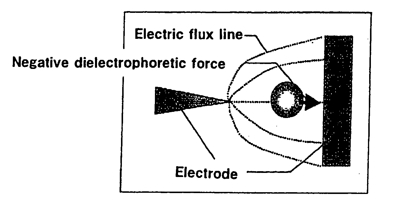
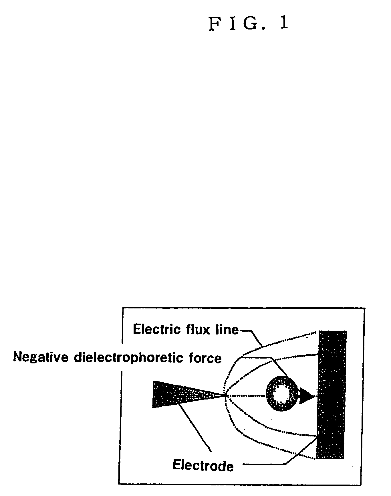
[0166] A dielectrophoretic test was conducted under the electric field that the beads show the negative dielectrophoresis on the electrode (electrode 2 in Table 1) prepared in Example 1, using beads having a diameter of 1 μm with the fluorescent-labeled surface thereof.

[0167] A sample solution with the beads suspended was dropped above the electrode substrate(hollow space), and afterward, a cover glass was put, and observation was made by an optical microscope.

[0168] As a result of observation of the dielectrophoretic test, it has been confirmed that the beads were concentrated in the h...

reference example 1

Manufacture of Dielectrophoretic Electrode Substrate

[0169] A multi-electrode array having a minimum gap of 7 μm, an electrode pitch of 20 μm, and the number of electrodes of 2016 (1008 pairs) was designed, and a photomask according to the design was made for manufacturing the electrode as follows.

[0170] On a glass substrate on which aluminum was deposited and to which a photoresist was applied, an electrode pattern as designed was drawn on an electron beam drawing machine, and then the photoresist was developed and the aluminum was etched to make the photomask.

[0171] The electrode substrate was manufactured according to the method described in T. Hashimoto, “Illustrative Photofabrication”, Sogo-denshi Publication (1985), as follows.

[0172] The photomask thus made was contacted tightly with the aluminum-deposited glass substrate to which a photoresist was applied, and then exposed to the electrode pattern with a mercury lamp. The electrode substrate was manufactured by developing ...


PUM

PropertyMeasurementUnit
lengthaaaaaaaaaa
inner diameteraaaaaaaaaa
sizeaaaaaaaaaa

Abstract

To provide an electrode for a dielectrophoretic apparatus in which a background detected by reflecting an excited light on an electrode present under the substance (molecule) is reduced and an S / N ratio is enhanced. Also, there is provided an dielectrophoretic apparatus, in an apparatus in which a liquid containing substances to be separated is present in a non-uniform electric field formed by a dielectrophoretic electrode, and separation is carried out by a dielectrophoretic force exerting on the substances, wherein the collecting ability of substances is enhanced. The present invention is characterized in that a vacant space is provided in an electrode whereby substances subjected to influence by a negative dielectrophoretic force can be concentrated in said vacant space of an electrode, or above or below portion of the space.

Description

CROSS REFERENCE TO RELATED APPLICATION [0001] This application is a division of Ser. No. 09 / 833,566, filed Apr. 13, 2001, which is based on Japanese Application No. 2000-112337 filed Apr. 13, 2000 and No. 2000-374210 filed Dec. 8, 2000.BACKGROUND OF THE INVENTION [0002] This invention relates to an electrode for a dielectophoretic apparatus, in which a background can be reduced to enhance an S / N (Signal / Noise) ratio in detecting a substance to be measured (molecules to be measured) by a fluorescent strength or the like, a method for manufacturing the same, an electrode constitution provided with the electrode, and a method for separating substances using the electrode. [0003] This invention further relates to an dielectrophoretic apparatus having an enhanced collecting ability, a method for manufacturing the same, and a method for separating substances using the apparatus. [0004] Processing technology of materials at scales of nanometer to micrometer by means of micromachining techn...

Claims


Application Information

Patent Timeline
Patent Type & Authority Applications(United States)
IPC IPC(8): B03C5/02
CPCB03C5/026
Inventor WASHIZU, MASAOKAWABATA, TOMOHISA
Owner WAKO PURE CHEMICAL INDUSTRIES
Why Eureka
Try Eureka