
Ceramic structures having hydrophobic coatings

a ceramic honeycomb and coating technology, applied in the direction of catalyst activation/preparation, metal/metal-oxide/metal-hydroxide catalysts, machines/engines, etc., can solve the problems of only using three-way catalysts, diesel emissions have come under attack in the united states, and the harmful effects of the environment and on humans, so as to reduce the absorption effect of ceramic honeycomb

Inactive Publication Date: 2005-07-21
CORNING INC
View PDF28 Cites 50 Cited by
  • Summary
  • Abstract
  • Description
  • Claims
  • Application Information

AI Technical Summary

Benefits of technology

[0014] The invention provides a catalyst support structure for use as either a NOx catalyst support or as a DPF. The catalyst support structure includes (i) a multicellular ceramic body, preferably a ceramic honeycomb, and more preferably a monolithic ceramic honeycomb made of cordierite or aluminum titanate, the ceramic honeycomb having an inlet end, an outlet end, and a multiplicity of mutually adjoining cells extending along the length of the honeycomb from the inlet end to the outlet end, the cells being separated from one another by porous walls, and, (ii) a hydrophobic coating adhering to the ceramic honeycomb which results in reduced absorption by the ceramic honeycomb when exposed to water-containing catalytic coating formulations and / or other aqueous media utilized in the process of applying the catalytic coating. In a preferred embodiment the hydrophobic coating is formed within or on an external skin portion of the ceramic honeycomb.

Problems solved by technology

However, diesel emissions have come under attack both in the United States and Europe, for their harmful effects on the environment and on humans.
However, unlike conventional engines which simply employ three-way catalysts, the diesel engine, which is a partial lean burn gasoline engine producing exhaust gas with an excess amount of oxygen, cannot employ only three-way catalysts because in order for these types of catalysts to function properly they require conditions where the air-fuel ratio is substantially stoichiometric.
Another significant challenge in lowering diesel emissions is controlling the levels of diesel particulate material present in the diesel exhaust stream.
As diesel filtration and catalyst products evolve and product performance demands change the catalyst coating process and chemistry, these changes are likely to result in incompatibilities between the catalyst coating process and the ceramic monoliths with exterior skin layers; whether in the form of NOx support substrates or in the form of DPFs.
One example of an incompatibility between monolith with applied exterior skin layers and catalyst coating processes is that the monolith and / or skin can exhibit excessive skin or coating cracking or spalling during or following the subsequent catalyst coating steps, due to absorption of coating liquid by the skin.
Other problems relating to monolith performance that have been observed following the application of catalyst coating media to ceramic monoliths include a substantial increase of the CTE (coefficient of thermal expansion) and / or increase of the elastic modulus of the monolith, both of these leading to decreased thermal shock performance (large axial and radial cracking) in the end use application.
In addition, the catalyst coating can reduce the strength of the monolith.

Method used


Image

  • Ceramic structures having hydrophobic coatings

Examples


example 1

[0046] In one embodiment, as described above, the passivating material is incorporated directly into the standard cold set cordierite cement which itself can thereafter be applied to the substrate material. Reported in Table I is the standard skin composition (in wt. %) and the same standard skin composition (also in wt. %) that has incorporated therein a methyl phenyl silicone resin passivating material which renders the cordierite skin or coating hydrophobic.

TABLE IStandard Skin CompositionPassivated Skin CompositionGround Cordierite62.5%Ground Cordierite55.5%(50 / 50 mixture of(50 / 50 mixture ofd50 = 40 μm / d50 = 40 μm / d50 = 12 μm)d50 = 12 μm)Methylcellulose Binder 0.5%Methylcellulose Binder 0.5%(Dow Corning(Dow CorningMethocel A4M)Methocel A4M)Colloidal Silica 4.0%Colloidal Silica 3.5%(Ludox)(Ludox)Aluminosilicate fiber  17%Aluminosilicate fiber  15%(Unifrax QF-180)(Unifrax QF-180)Deionized Water  16%Deionized Water19.5%Rheology modifier 0.5%(Alcogum SL-70)Silicone Resin Sol'n 5.5...

example 2

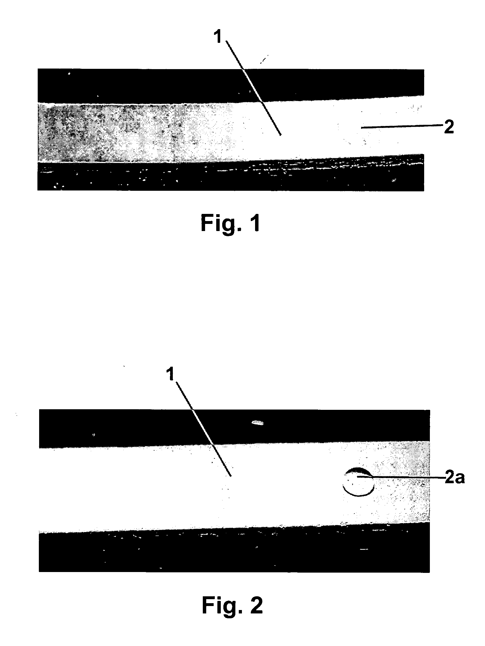
[0049] Four cordierite ceramic samples comprised of the standard cordierite skin composition detailed in Table I are produced; in particular 2 mm thick (100 mm×200 mm) sheets are formed. The first, for comparison, is not coated with a passivating material, while the other three sheets are coated with the inventive hydrophobic coatings. The passivating materials used for Inventive Samples A, B and C reported in Table II included, respectively, silicone resin (Dow Corning DC233 Silicone Resin dissolved in dibasic ester of diethyl adipate, in a 2:1 weight ratio), tung oil, and a copolymer consisting of Michem 4983R ethylene acrylic acid copolymer. For each of the inventive samples the passivating material is applied to the standard skin composition sheet (same wt % as above) by dipping the substrates for a time sufficient to saturate the sheets—approximately 1 min.

[0050] Each of the four substrate samples (one standard and three coated) are immersed in a cerium nitrate (CeNO3)3 cataly...

example 3

[0052] Sixty two ceramic honeycomb samples are produced (31 comprising cordierite; 31 comprising aluminum titanate); each of the samples being comprised of an 8 mm×8 mm×50 mm bar cut from a ceramic honeycomb of corresponding composition. Each of 31 different passivating coating materials, as detailed in Table III, is applied to a cordierite honeycomb and aluminum titanate honeycomb bar. To apply these coating materials, each of the substrates is immersed in a room temperature dilute coating material solution for two minutes. The coating materials / passivation coating concentration utilized are detailed in Table III; 10% IPA representing a 10% isopropyl alcohol dilute solution, 10% H2O representing a 10% deionized water dilute solution and 100% representing a full strength material solution. The excess coating is then blown out of the samples using compressed nitrogen. The coated samples are then dried in a recirculating oven at 60° C. for a minimum of two hours.

[0053] The test used ...


PUM

PropertyMeasurementUnit
Temperatureaaaaaaaaaa

Abstract

A catalyst support structure for use as either a NOx catalyst support or as a DPF including (i) a multicellular ceramic body, preferably a monolithic ceramic honeycomb composed e.g., of cordierite or aluminum titanate, and (ii) a hydrophobic coating on at least the exterior surface thereof which results in a ceramic honeycomb exhibiting reduced or low absorption when exposed to both liquid catalytic coating media and aqueous media utilized in the process of applying the catalytic coating. In a preferred embodiment the hydrophobic coating is formed within or on an applied external skin layer provided on the multicellular ceramic body.

Description

[0001] This application claims the benefit of U.S. Provisional Application No. 60 / 533,838, filed Dec. 31, 2003, entitled “Cordierite Structures Having An External Hydroscopic Coating”, by Max P. Bliss, et al.BACKGROUND OF THE INVENTION [0002] 1. Field of the Invention [0003] The invention relates to catalyst support structures having a passivated or hydrophobic layer, and particularly cordierite or aluminum titanate catalyst support structures / diesel filters having a hydrophobic external coating. [0004] 2. Discussion of the Related Art [0005] Recently much interest has been directed towards the diesel engine due to its efficiency, durability and economical aspects. However, diesel emissions have come under attack both in the United States and Europe, for their harmful effects on the environment and on humans. As such, stricter environmental regulations will require diesel engines to be held to the same standards as gasoline engines. Therefore, diesel engine manufacturers and emissio...

Claims


Application Information

Patent Timeline
IPC IPC(8): B01D53/94B01J20/00B01J21/04B01J23/00B01J23/08B01J23/10B01J35/04B01J37/02C03C3/04C04B35/10C04B35/14C04B35/16C04B35/18C04B35/185C04B35/20C04B35/22C04B35/44C04B35/636C04B35/80C04B38/00C04B41/52C04B41/89F01N3/022F01N3/28
CPCB01D2258/012Y02T10/20B01J35/04B01J37/0217B01J37/0242C04B35/185C04B35/6263C04B35/6365C04B35/803C04B38/0009C04B41/009C04B41/52C04B41/89C04B2111/0081C04B2111/0087C04B2235/3418C04B2235/422C04B2235/483C04B2235/5228C04B2235/5436C04B2235/5472C04B2235/96F01N3/0222F01N3/2828F01N2330/06F01N2510/14B01J23/10C04B35/195C04B38/0054C04B35/478C04B14/4656C04B41/5037C04B41/5089C04B41/4961C04B41/522C04B2103/65C04B41/455C04B41/5045Y02T10/12C04B35/80B01J35/56
Inventor BLISS, MAX P.BOOKBINDER, DANA C.PAISLEY, ROBERT J.WARREN, CHRISTOPHER J.
Owner CORNING INC
Learn More