Solid Oxide Fuel Cell With Internal Reforming, Catalyzed Interconnect For Use Therewith, and Methods

a fuel cell and internal reforming technology, applied in the direction of cell components, final product manufacturing, sustainable manufacturing/processing, etc., can solve the problems of increasing the volume, cost and operating complexity of the total sofc power generation system, consuming additional energy, and lack of catalytic surface area for sufficient reforming activity, etc., to achieve enhanced geometrical and catalytic surface area, the effect of reducing the carbonaceous deposi

Active Publication Date: 2005-08-04
CUMMINS ENTERPRISE LLC
View PDF14 Cites 76 Cited by
  • Summary
  • Abstract
  • Description
  • Claims
  • Application Information

AI Technical Summary

Benefits of technology

[0010] This invention addresses the above described need in the art by providing a catalyzed interconnect for placement between an anode and a current collector in a fuel cell. The catalyzed interconnect is coated with a catalytic coating comprising a catalyst for catalyzing conversion of hydrocarbon fuel to hydrogen rich reformate within a fuel cell. This interconnect improves efficiency o

Problems solved by technology

Such external reforming processes invariably add volume, cost and operating complexity into the total SOFC power generation system.
Moreover, they often consume additional energy in the process of converting hydrocarbons.
There are several challenges currently existing in the internal reforming approach.
The first one is a lack of catalytic surface area for sufficient reforming activity.
Since the anode in an SOFC usually consists of low surface area cermet material as the result of the type of metal oxide used and high temperature preparation, the catalyst area by anode alone is not sufficient for the reforming need.
The second challenge in internal reforming is the formation of carbonaceous deposit over the surface of the anode, which normally contains nickel.
This problem is compounded when liquid hydrocarbon fuels are used.
The carbon formation blocks fuel passage to active sites in the anode and results in performance decay of SOFC.
However, low activity of copper and complexity

Method used


Image

  • Solid Oxide Fuel Cell With Internal Reforming, Catalyzed Interconnect For Use Therewith, and Methods
  • Solid Oxide Fuel Cell With Internal Reforming, Catalyzed Interconnect For Use Therewith, and Methods
  • Solid Oxide Fuel Cell With Internal Reforming, Catalyzed Interconnect For Use Therewith, and Methods

Examples


Embodiment Construction

[0020] As summarized above, this invention encompasses a catalyzed anodic interconnect, a solid oxide fuel cell with internal reforming including such a catalyzed anodic interconnect, a method for operating an SOFC, and a method for making a catalyzed anodic interconnect. Embodiments of this invention are described in detail below and illustrated in FIGS. 1-4.

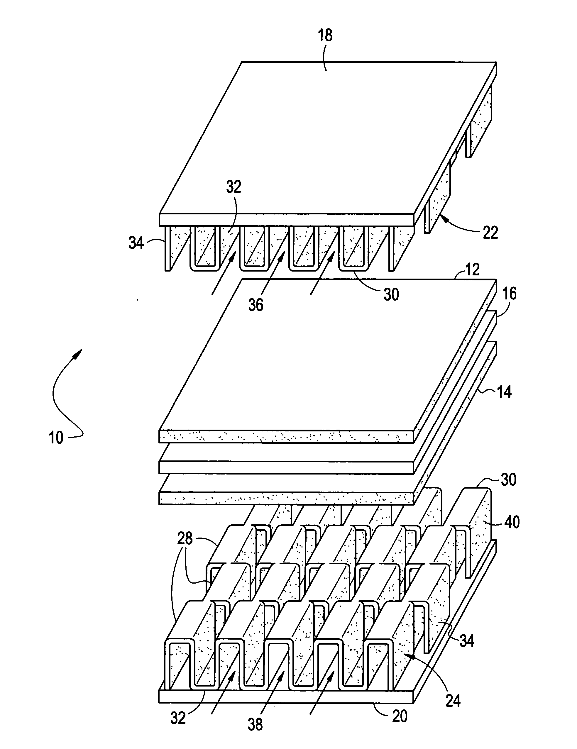
[0021] A single SOFC cell 10 made in accordance with an embodiment of this invention is illustrated in FIG. 1 and has integrated internal reforming capability. Generally, the SOFC 10 comprises a cathode 12, an anode 14, solid electrolyte 16 disposed between the anode and the cathode, a cathodic current collector 18, an anodic current collector 20, a cathodic interconnect 22, and an anodic interconnect 24.

[0022] The cathode 12 is in the form of thin ceramic layer and is suitable for fuel cell operation. It is desirably made of lanthanum strontium manganite (LSM), lanthanum strontium ferrite (LSF), and cobaltites. The anode 14 ...


PUM


Abstract

A catalyzed interconnect for an SOFC electrically connects an anode and an anodic current collector and comprises a metallic substrate, which provides space between the anode and anodic current collector for fuel gas flow over at least a portion of the anode, and a catalytic coating on the metallic substrate comprising a catalyst for catalyzing hydrocarbon fuel in the fuel gas to hydrogen rich reformate. An SOFC including the catalyzed anodic inter-connect, a method for operating an SOFC, and a method for making a catalyzed anodic interconnect are also disclosed.

Description

FEDERAL RESEARCH STATEMENT [0001] This invention was made with government support under DE-PS26-00NT40854 Department of Energy. This government has certain rights in this invention.BACKGROUND OF INVENTION [0002] Solid oxide fuel cells (SOFC) have demonstrated great potential for future power generation with high efficiency and low emission. Due to relatively high operating temperature and stable electrolyte material, SOFCs can be operated with the hydrocarbon reformate fuel containing higher carbon monoxide and carbon dioxide content than other types of fuel cell systems. Furthermore, the SOFCs can be integrated with a gas turbine to further enhance the overall system efficiency through co-generation. [0003] At present, an SOFC stack generally requires an upstream, separate reforming process when hydrocarbons such as natural gas, gasoline, diesel, jet fuel, and the like, are used as fuel for the SOFCs. External reforming converts hydrocarbons into a mixture containing hydrogen and c...

Claims


Application Information

Patent Timeline
IPC IPC(8): B05D5/12H01M4/86H01M4/92H01M8/02H01M8/06H01M8/12
CPCH01M4/92H01M8/021H01M8/0228H01M8/0232H01M8/0247Y02E60/525H01M8/0293H01M8/0637H01M2008/1293Y02E60/50H01M8/0258Y02P70/50
Inventor LIU, DI-JIAGUAN, JIEMINH, NGUYEN
Owner CUMMINS ENTERPRISE LLC
Why Eureka
Try Eureka