

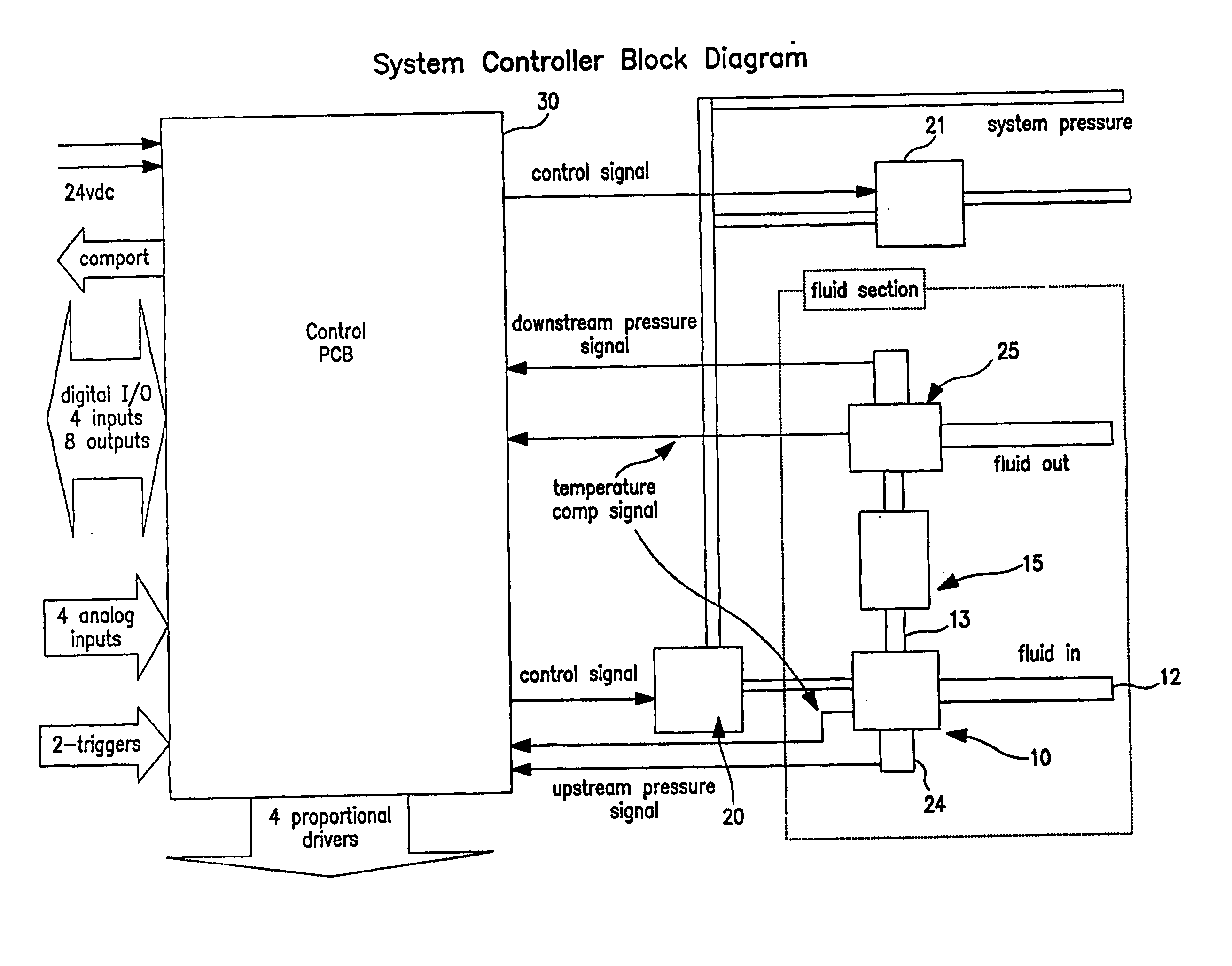
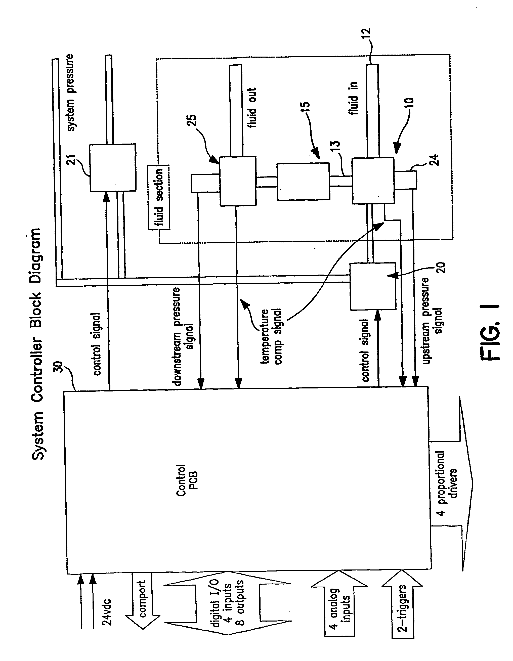
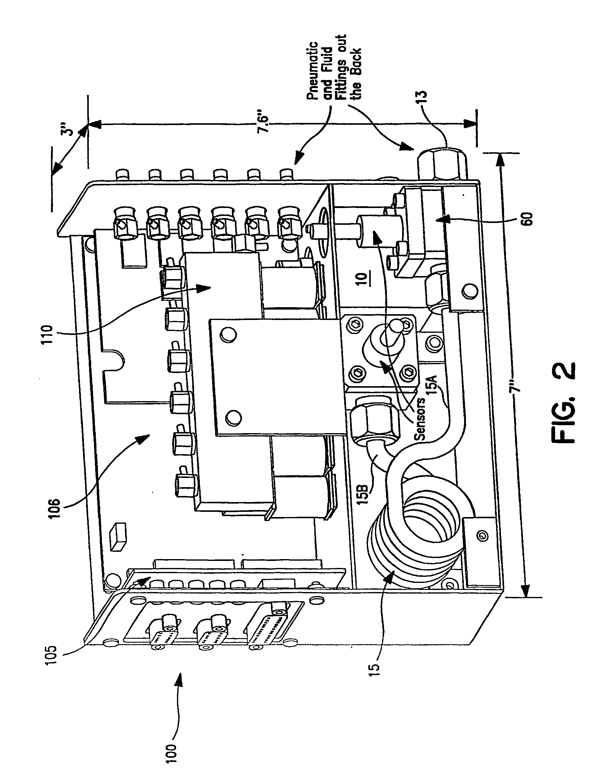
Liquid flow controller and precision dispense apparatus and system
- Summary
- Abstract
- Description
- Claims
- Application Information
AI Technical Summary
Benefits of technology
Problems solved by technology
Method used
Image

Examples
example 1
[0121] The system was set up so that a known differential pressure and a fixed dispense time could be inputted to the controller, and a dispense could be subsequently triggered from a laptop computer. The resultant output flow of deionized water was captured in a container and weighed using a precision scale to determine its mass. Using the mass of each dispense combined with the known density of the fluid material, the volume of each dispense was calculated. Combining the volume dispensed with the known dispense time resulted in a flow rate determination. Five different viscosities were checked, ranging from about 0.92 to about 9.5 centipoise. The results are shown graphically in FIG. 10.
example 2
[0122] Three different valves were tested for hysteresis, including two commercially available valves, and the valve of the present invention shown in FIGS. 8A-8D. The valve actuation pressure was varied up and down and the pressure inside the test system was measured in steps up and down through the valve actuation pressure range and plotted as voltage. More specifically, the test set-up was a closed system of the valve and downstream pressure sensor, with the valve under constant pressure and the pressure sensor monitoring the change in pressure downstream of the valve as the valve moved through its range of closed to full open and back again to closed.
[0123] The results are shown graphically in FIGS. 9A, 9B and 9C. In each graph, the curve farthest to the right represents the data for varying the pressure from low to high, and the curve to the left is the result of varying pressure from high to low. The difference between the curves represents the amount of hysteresis. Thus, as ...
example 3
[0124] This example illustrates the use of an embodiment of the present invention to measure and control liquid flow to enable the delivery of discrete volumes of fluid for chemical mechanical planarization substrate processing. More specifically, this example demonstrates how an embodiment of the present invention may be used to measure and control liquid flow to enable the delivery of discrete volumes of a polishing fluid to a substrate.
[0125] Chemical mechanical polishing is useful in the manufacture of optical lenses. Chemical mechanical planarization is useful in the manufacture of semiconductor devices. Polishing fluids may be acidic or basic and may contain abrasives such as silica or alumina. A fluid useful for polishing silicon dioxide includes silica slurry in an aqueous potassium hydroxide solution; a fluid useful for polishing copper metal includes an oxidizer such as hydrogen peroxide, an inhibitor such as benzotriazole, and an aqueous solution of an organic acid such ...
PUM
 Abstract
Description
Claims
Application Information