
Method and apparatus for compressing a gas to a high pressure

a gas compression and high pressure technology, applied in mechanical equipment, positive displacement liquid engines, pumps, etc., can solve the problems of increasing the manufacturing and maintenance costs of multi-stage systems, the inability to continue the operation of successive stages, and the increase of the cost of multi-stage compressors with the number of stages, so as to facilitate the reduction of the proportion of dead space volume, improve the efficiency of compressors, and improve the length to diameter ratio

Active Publication Date: 2005-08-18
WESTPORT FUEL SYST CANADA INC
View PDF7 Cites 35 Cited by
  • Summary
  • Abstract
  • Description
  • Claims
  • Application Information

AI Technical Summary

Benefits of technology

[0022] supplying the hydraulic fluid to the drive chamber whereby the hydraulic fluid within the drive chamber is at a higher pressure than the gas within the compression chamber, causing the piston to move to increase the volume of the drive chamber and reduce the volume of the compression chamber thereby increasing the pressure of the gas held within the compression chamber;
[0062] As disclosed, the apparatus can be combined with one or more of the disclosed features to reduce gas temperature and improve thermodynamic efficiency.

Problems solved by technology

This arrangement does not allow continuous operation of successive stages because this would not allow sufficient time for cooling the gas between stages.
The cost of a multi-stage compressor increases with the number of stages because separate compressor units are required for each stage.
Each compression stage requires its own drive, piping and cooling stage, which adds to the manufacturing and maintenance costs associated with such multi-stage systems.
Conventional mechanically driven piston compressors that employ a rotating crankshaft to drive the compressor piston are limited to designs with relatively short piston strokes.
As the length to diameter ratio increases, it becomes harder to maintain alignment of the piston rod and piston, which can cause faster wearing around the seals.
A higher length to diameter ratio also results in increased piston rod weight because of the increased rod length and the need to design against buckling.
Notwithstanding the problems with alignment and weight, for some applications, such as the aforementioned vehicular fuel compressor application, such an elongated space is not conveniently available.
However, high pressure gas compressors are unknown that can compress a gas by a ratio of five to one or more, in a single cycle of a single stage, and under significantly less than isentropic conditions.
As the compression ratio increases the cumulative temperature rise during the compression cycle also increases, and under near isentropic conditions compression is inefficient.
For example, for a vehicular application, a light weight compressor apparatus can reduce vehicle weight and improve overall vehicle efficiency, whereas, reduced weight can not have similar benefits for a compressor installed at a stationary installation.
A compressor failure can result in costly downtime or stranding a vehicle, while inefficient operation increases operating costs.
In addition, with an engine that is the prime mover for a vehicle, higher fuel consumption reduces vehicle range and limits the routes that a vehicle can be used for.
For engines used for power generation, the efficiency of each component effects overall efficiency, and low efficiency can have significant economic consequences when an engine is run on a continuous basis and under high load conditions.

Method used


Image

  • Method and apparatus for compressing a gas to a high pressure
  • Method and apparatus for compressing a gas to a high pressure
  • Method and apparatus for compressing a gas to a high pressure

Examples


example 1

[0116] The graph shown in FIG. 6 represents data collected from a gas compressor that employed a free floating hydraulically driven piston. The compressor cylinder had a stroke length of 10 1 / 4 inches (about 261 mm) and a bore diameter of 1 3 / 8 inches (about 34.9 mm), which corresponds to a length to diameter ratio of about 7.5:1. The cylinder was cooled by ambient air that had a temperature of about 10 degrees Celsius.

[0117] The graph of FIG. 6 plots temperature rise in degrees Celsius on the vertical axis against compressor speed in cycles per minute. Nitrogen gas was supplied to the compressor at a temperature of about 0 degrees Celsius.

[0118] Table 2 below sets out specific parameters associated with each of the data points.

TABLE 2Compressor Speed (CPM)18.814.49.44.8Inlet Pressure (MPa)3.94.14.14.2Outlet Pressure (MPa)20.620.920.620.3Mass Flow (kg / hr)25.819.612.66.7

[0119] Plotted as a straight line at about 160 degrees Celsius is the temperature rise associated with isentrop...

example 2

[0123] The data set out in table 3 below was collected from three experiments done with a larger gas compressor that employed a free floating hydraulically driven piston to compress natural gas. The compressor cylinder had a stroke length of 54 inches (about 1370 mm) and a bore diameter of 2 1 / 2 inches (about 64 mm), which corresponds to a length to diameter ratio of about 21.6:1.

[0124] A coolant consisting of 50% glycol and 50% water was circulated through a cooling jacket surrounding the compressor cylinder. The temperature of the coolant supplied to the water jacket was about 15 degrees Celsius.

[0125] The hydraulic system employed a constant power hydraulic pump, resulting in piston velocity automatically decreasing as resistance to piston movement increased with increasing gas pressure.

[0126] The three experiments were done with different cycle frequencies (measured in cycles per minute) and different compression ratios.

TABLE 3Experiment#1#2#3Cycle Frequency3512Average Pist...


PUM


Abstract

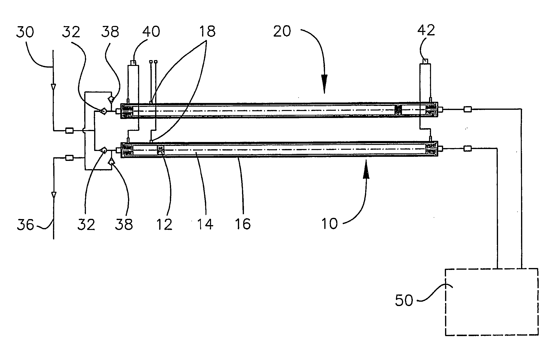
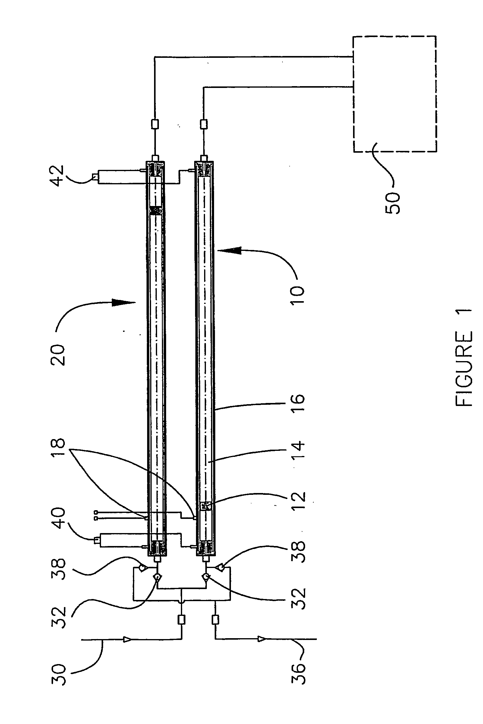
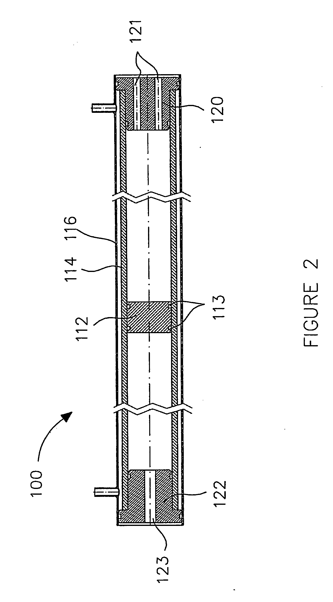
A method is provided for compressing a gas in a single cycle and in a single cylinder to a pressure of at least 17.2 Mpa with a compression ratio of at least about five to one. The method further comprises dissipating heat from the cylinder during the compression stroke whereby the gas is discharged with a temperature significantly less than isentropic. The apparatus comprises a hollow cylinder and a reciprocable free-floating piston disposed therein. The piston divides the cylinder into: (a) a compression chamber within which a gas can be introduced, compressed, and discharged; and, (b) a drive chamber, into which a hydraulic fluid can be introduced and removed for actuating the piston. The apparatus further comprises a piston stroke length to piston diameter ratio of at least seven to one. For operating the apparatus with a compression ratio of at least five to one, an outlet pressure of at least 17.2 Mpa, and a gas discharge temperature significantly less than isentropic, the apparatus can further comprise a variable displacement hydraulic pump for controlling piston velocity, an electronic controller for maintaining an average piston velocity that is less than 0.5 feet per second, and a heat dissipator for dissipating heat from the cylinder.

Description

FIELD OF THE INVENTION [0001] The present invention relates to a method and apparatus for compressing a gas to a high pressure. More particularly, the method comprises compressing a gas in a single cycle and in a single cylinder to a high pressure with a compression ratio of at least about five to one, while dissipating heat from the cylinder during the compression stroke, and discharging the gas with a temperature significantly less than isentropic. The apparatus comprises a free-floating piston disposed within the cylinder and a piston stroke length to piston diameter of at least seven to one. BACKGROUND OF THE INVENTION [0002] A conventional compressor that is operable to increase the pressure of a gas to a high pressure by a ratio of more than four to one typically employs two stages of compression. Conventional compressors operate under near isentropic conditions and the use of multiple stages allows heat exchangers, also known as intercoolers, to be employed between stages to ...

Claims


Application Information

Patent Timeline
IPC IPC(8): F04B9/107F04B9/117F04B31/00F04B39/06F04B41/00
CPCF04B9/107F04B9/1176F04B2201/0201F04B39/064F04B39/066F04B31/00
Inventor URSAN, MIHAIGRAM, ANKERGAVRIL, GABRIELHESSAMI, SHAHINLOCKLEY, IAN
Owner WESTPORT FUEL SYST CANADA INC
Learn More