Implantable biosensor system, apparatus and method

a biosensor and implantable technology, applied in the field of medical devices, can solve the problems of inadequate periodic information, less than optimal, and insufficient glucose in urine measurement, and achieve the effect of enhancing the biocompatibility of the biosensor and enhancing the volume of glucose oxidas

Inactive Publication Date: 2005-08-25
SORENSON DEVMENT
View PDF14 Cites 228 Cited by
  • Summary
  • Abstract
  • Description
  • Claims
  • Application Information

AI Technical Summary

Benefits of technology

[0022] Desirably, an exterior coating of a negatively charged polymer is applied to the working electrode. One operable negatively charged polymer includes sulfonated polyethersulfone. It is also sometimes desirable to provide a microscopically roughed-up outer surface on the coating to enhance biocompatibility of the biosensor with tissue of the subject's body. Desirable surface texture is formed by elements having a size of between about 5 and 50 microns. Multifiber cores typically include a plurality of spaces between the fibers operable to carry glucose oxidase whereby to enhance a volume of glucose oxidase associated with a working electrode.

Problems solved by technology

Formerly, glucose in urine was measured, though recognized as less than adequate due to the time delay inherent in the metabolism and voiding process.
However, the dynamic nature of blood glucose chemistry and the complexity of factors influencing blood sugar levels render such periodic information less than optimal.
A deleterious impact on physiology follows either such disequilibrium.
Hypoglycemia, on the other hand, poses the more serious short-term danger.
Hypoglycemia can occur at any time of the day or night and can cause the patient to lose consciousness.
Guarding against hypoglycemia may require frequent monitoring of blood glucose levels and render the skin-prick approach tedious, painful and, in some cases, impractical.
Even diligent patients who perform finger-sticking procedures many times each day achieve only a poor approximation of continuous monitoring.
A risk of infection is associated with percutaneous biosensors, and they must typically be replaced at regular intervals because of the risk of infection at the insertion site.
Another problem with implanted sensors is irritation of the tissues surrounding the implanted biosensors.
Such irritation is typically due, in part, to the lateral rigidity of prior art biosensors.
Related to this problem is the scarring of surrounding tissue due not only to rigidity but also to abrupt edges associated with the implants.
However, scar tissue can be materially detrimental to the sensor function in the vicinity of the working electrode because it impedes the diffusion of oxygen and glucose.
Further, to protect itself against a perceived invader, the body commonly experiences a foreign body reaction by encapsulating the implanted biosensors with protein, which may shorten the life of the implant and adversely affect the accuracy of information provided.
The size of the sensor may also be regarded as a problem; smaller is better for comfort.
Further yet, interfering compounds, such as, for example, ascorbic acid, and acetaminophen, can reduce the accuracy of prior art amperometric glucose sensors given the membranes selected historically to envelop such sensors.
Additionally, the quantity of dissolved oxygen is limited at high glucose concentrations, thus leading to nonlinear output of sensor signals at high glucose concentrations.

Method used


Image

  • Implantable biosensor system, apparatus and method
  • Implantable biosensor system, apparatus and method
  • Implantable biosensor system, apparatus and method

Examples


embodiment 10

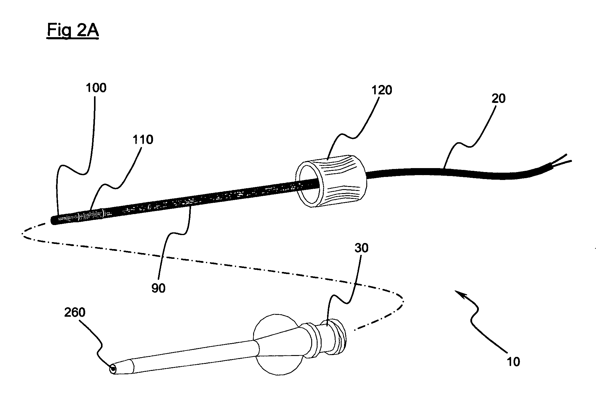
[0060] The preferred embodiment 10 illustrates the working electrode 100 as being structured in the form of coils. However, it is only necessary that the working electrode 100 be in length substantially not less than the leading portion 280 when the leading portion 280 is laterally deflected to a maximum extent. Such a limitation is operable to resist separation of an electrically conductive path from the electrode due to bending of the biosensor. Correspondingly, whereas in a preferred embodiment the reference electrode 110 is illustrated as being in the form of coils, in essence a working electrode 110 may be in length substantially not less than the trailing portion 290 when the trailing portion 290 is laterally deflected to a maximum extent.

[0061]FIGS. 6A-6D illustrate an alternative preferred embodiment of a biosensor, generally indicated at 330, including an introducer catheter, generally indicated at 340. The biosensor 330 includes a working electrode, generally 350, typicall...

embodiment 330

[0062] The introducer catheter 340, like the introducer catheter 30, includes a lumen that may be thought of as an interior cannula lumen 450. Furthermore, the illustrated introducer catheter 340 presents an advanced end 460 designed for subcutaneous or other intra-tissue placement, an opposite end, generally 470, and a cannula wall 480 defining the interior cannula lumen 450 and comprising an exterior surface 490. The exterior surface 490 and the interior cannula lumen 450 extend between the advanced end 460 and the opposite end 470. In the biosensor embodiment 330, a reference electrode 500 is associated with the exterior surface 490 of catheter 340 in the vicinity of the advanced end 460. Electrode 500 may take other forms, such as a film, band, etching, printed or imprinted layer, or a shell or coating. The interior cannula lumen 450 is of sufficient cross-sectional diameter to pass the biosensor 330. The advanced end 460 and exterior surface 490 of the introducer catheter 340 a...


PUM

PropertyMeasurementUnit
diameteraaaaaaaaaa
diameteraaaaaaaaaa
diameteraaaaaaaaaa

Abstract

An implantable biosensor assembly and system includes an enzymatic sensor probe from which subcutaneous and interstitial glucose levels may be inferred. The assembly may be associated by direct percutaneous connection with electronics, such as for signal amplification, sensor polarization, and data download, manipulation, display, and storage. The biosensor comprises a miniature probe characterized by lateral flexibility and tensile strength and has a large electrode surface area for increased sensitivity. Irritation of tissues surrounding the probe is minimized due to ease of flexibility and small cross section of the sensor. Foreign body reaction is diminished due to a microscopically rough porous probe surface.

Description

CROSS-REFERENCE TO RELATED APPLICATION [0001] This application is a continuation of U.S. application Ser. No. 10 / 401,224, filed Mar. 26, 2003, the contents of the entirety of which are herein incorporated by this reference.TECHNICAL FIELD [0002] This invention relates generally to medical devices and associated methods such as measuring glucose for ongoing diabetes management. The invention described herein can also be used for enzymatic determination of other analytes. This invention provides a particularly useful implantable biosensor. BACKGROUND OF THE INVENTION [0003] Heretofore, treatment and management of diabetes has been undertaken through many and varied techniques. Formerly, glucose in urine was measured, though recognized as less than adequate due to the time delay inherent in the metabolism and voiding process. Currently, the approach predominantly used for self-monitoring of blood glucose requires periodic pricks of the skin with a needle, whereby a blood sample is obta...

Claims


Application Information

Patent Timeline
Patent Type & Authority Applications(United States)
IPC IPC(8): A61B5/00A61B5/05G01NG01N27/26
CPCA61B5/14532A61B2560/045A61B5/6852A61B5/14865
Inventor HITCHCOCK, ROBERT W.SORENSON, JAMES L.
Owner SORENSON DEVMENT
Why Eureka
Try Eureka