

Method for attaching a porous metal layer to a metal substrate
a technology of porous metal and metal substrate, which is applied in the direction of prosthesis, soldering apparatus, manufacturing tools, etc., can solve the problems of difficult metallurgy bonding between two components, large contact distance, and difficulty in sintering or diffusion bonding, so as to improve the bond strength and corrosion resistance
Active Publication Date: 2005-08-25
ZIMMER INC
View PDF40 Cites 78 Cited by
- Summary
- Abstract
- Description
- Claims
- Application Information
AI Technical Summary
Benefits of technology
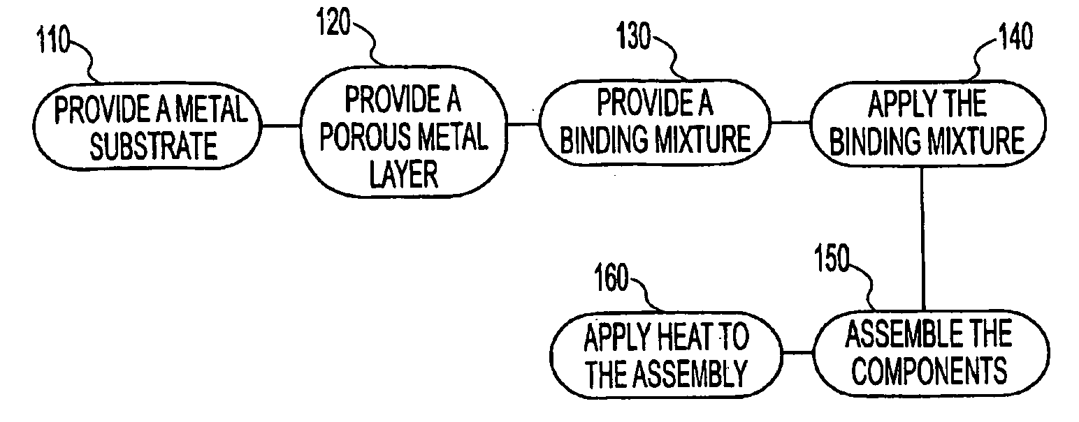
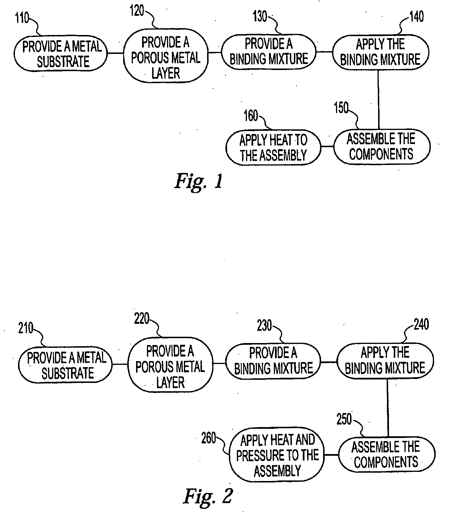
The present invention provides a method for bonding a porous metal layer to a titanium or cobalt alloy substrate using a sintering or diffusion bonding process. The method involves applying a binding mixture to the substrate or porous metal, placing them together, and subjecting them to heat and / or pressure to create a strong bond. The resulting bond has good surface contact between the porous metal and the substrate, and the bond strength is enhanced compared to other methods. This method can be used to create orthopedic implants with a porous metal surface on titanium or cobalt alloy substrates that have enhanced bond strength and corrosion resistance. The method is simple and protects the metallurgical properties of the component alloys.
Problems solved by technology
In spite of the value of using a porous layer in orthopedic implants, bonding porous metal to a metal substrate such as cobalt alloy or titanium alloy has been difficult, especially in the case of HEDROCEL.
The reason for this difficulty is that metallurgically bonding two components generally requires a large amount of contact between the surfaces at which the bond is desired.
The porosity of HEDROCEL results in sparse contact with an opposing metal substrate, thereby making sintering or diffusion bonding difficult.
Moreover, this porosity also makes it difficult to maintain the narrow dimensioning tolerances for machined HEDROCEL, components.
Method used
View moreImage
Smart ImageViewing Examples

Examples
examples
[0070]
SUBSTRATEPOROUSCYCLECYCLEENVIRON-CLAMPINGMATERIALLAYERTEMPERATURETIMEMENTPRESSUREBINDING MIXTURETi—6AL—VHEDROCEL 955° C.2 cycles at 4 hours eachArgon400 p.s.i.68% PVA + 32% (10% PVA,90% water solution)Ti—6AL—VHEDROCEL 955° C.2 cycles at 4 hours eachHelium400 p.s.i.68% PVA + 32% (10% PVA,90% water solution)Ti—6AL—VHEDROCEL 955° C.2 cycles at 4 hours eachArgon400 p.s.i.N / ATi—6AL—VMachined 350° C. (debind) +3 hours (debind) +0.01 TorrN / A68% PVA + 32% (10% PVA,HEDROCEL1200° C.4 hours (sintering)90% water solution)(sintering)Co—Cr—MoMachined1094° C.2 cycles at 4 hours each0.01 Torr400 p.s.i.68% PVA + 32% (10% PVA,HEDROCEL90% water solution)
4001-0035 (ZM0473B1) utility application 04-10-05A
Login to View More PUM
| Property | Measurement | Unit |
|---|---|---|
| thickness | aaaaa | aaaaa |
| temperature | aaaaa | aaaaa |
| pressure | aaaaa | aaaaa |
Abstract
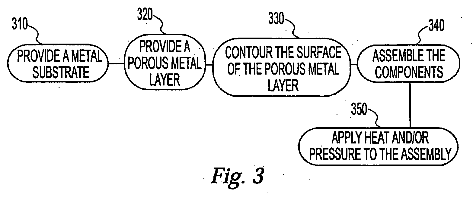
A method for attaching a porous metal layer to a dense metal substrate, wherein the method is particularly useful in forming orthopedic implants such as femoral knee components, femoral hip components, and / or acetabular cups. The method, in one embodiment thereof, comprises providing a solid metal substrate; providing a porous metal structure; contouring a surface of the porous metal structure; placing the porous structure against the substrate such that the contoured surface of the porous metal structure is disposed against the substrate, thereby forming an assembly; applying heat and pressure to the assembly in conjunction with thermal expansion of the substrate in order to metallurgically bond the porous structure and the substrate; and removing mass from the substrate after the porous structure is bonded to the substrate, thereby finish processing the assembly.
Description
CROSS-REFERENCE TO RELATED APPLICATION(S) [0001] This is a continuation-in-part of U.S. patent application Ser. No. 10 / 455,846, filed Jun. 6, 2003, entitled “METHOD FOR ATTACHING A POROUS METAL LAYER TO A METAL SUBSTRATE,” which claims the benefit of U.S. Provisional Patent Application No. 60 / 389,615, filed Jun. 18, 2002. FIELD OF THE INVENTION [0002] The present invention relates to orthopedic implants of the type having a porous surface into which bone tissue can grow or bone cement can enter and, more particularly, to a method of bonding a porous metal structure, such as porous titanium or porous tantalum onto a metal substrate preferably comprising a titanium-based or cobalt-based alloy. BACKGROUND [0003] Orthopedic implant devices commonly include a porous structure of desired thickness, generally 0.5 to 5.0 mm, on the bone contacting surface of the implant to promote bone growth there through and to enhance attachment of the device to adjacent bone tissue. Growth of bone into ...
Claims
Login to View More Application Information
Patent Timeline
 Patent Type & AuthorityApplications(United States)
IPC IPC(8): A61F2/00A61F2/30A61F2/34A61F2/38A61L27/04A61L27/30A61L27/56B22F7/00B22F7/06C23C26/00
CPCA61F2/30767A61F2/30907A61F2/3094A61F2/3859A61F2002/30787A61F2002/30967A61F2002/30968A61F2002/30978A61F2002/3401A61F2310/00023A61F2310/00029A61F2310/00407A61F2310/00544A61L27/04A61L27/30A61L27/56B22F7/004B22F7/064C23C26/00Y10T29/49861B23P23/00
InventorCHARLEBOIS, STEVENGILBERTSON, LESLIEHAWKINS, MICHAELMEDLIN, DANASHETTY, H.ZAWADZKI, STEVEN
OwnerZIMMER INC