
Drug coating with topcoat

a topcoat and drug technology, applied in the field of topcoats for drugs, can solve the problems of increasing the thickness of the coating, reducing the effective drug loading, and increasing the coating thickness, so as to reduce the burst effect, prolong the release time, and reduce the effect of drug elution

Inactive Publication Date: 2005-09-22
BOSTON SCI SCIMED INC
View PDF99 Cites 16 Cited by
  • Summary
  • Abstract
  • Description
  • Claims
  • Application Information

AI Technical Summary

Benefits of technology

[0027] It is desirable that the topcoat be substantially free of connected pores or porosigens (materials which can elute during implantation and form pores). The addition of a porous membrane as a top coat will increase the coating thickness and reduce the overall drug loading. Also, the release of porosigens into the body can be undesirable since it introduces additional foreign materials into the body, which can cause the patient to have adverse reactions.
[0032] The coating may be applied by dipping or spraying using evaporative solvent materials of relatively high vapor pressure to produce the desired viscosity and quickly establish coating layer thicknesses. The preferred process is predicated on reciprocally spray coating a rotating radially expanded stent employing an air brush device. The coating process enables the material to adherently conform to and cover the entire surface of the filaments of the open structure of the stent but in a manner such that the open lattice nature of the structure of the braid or other pattern is preserved in the coated device.
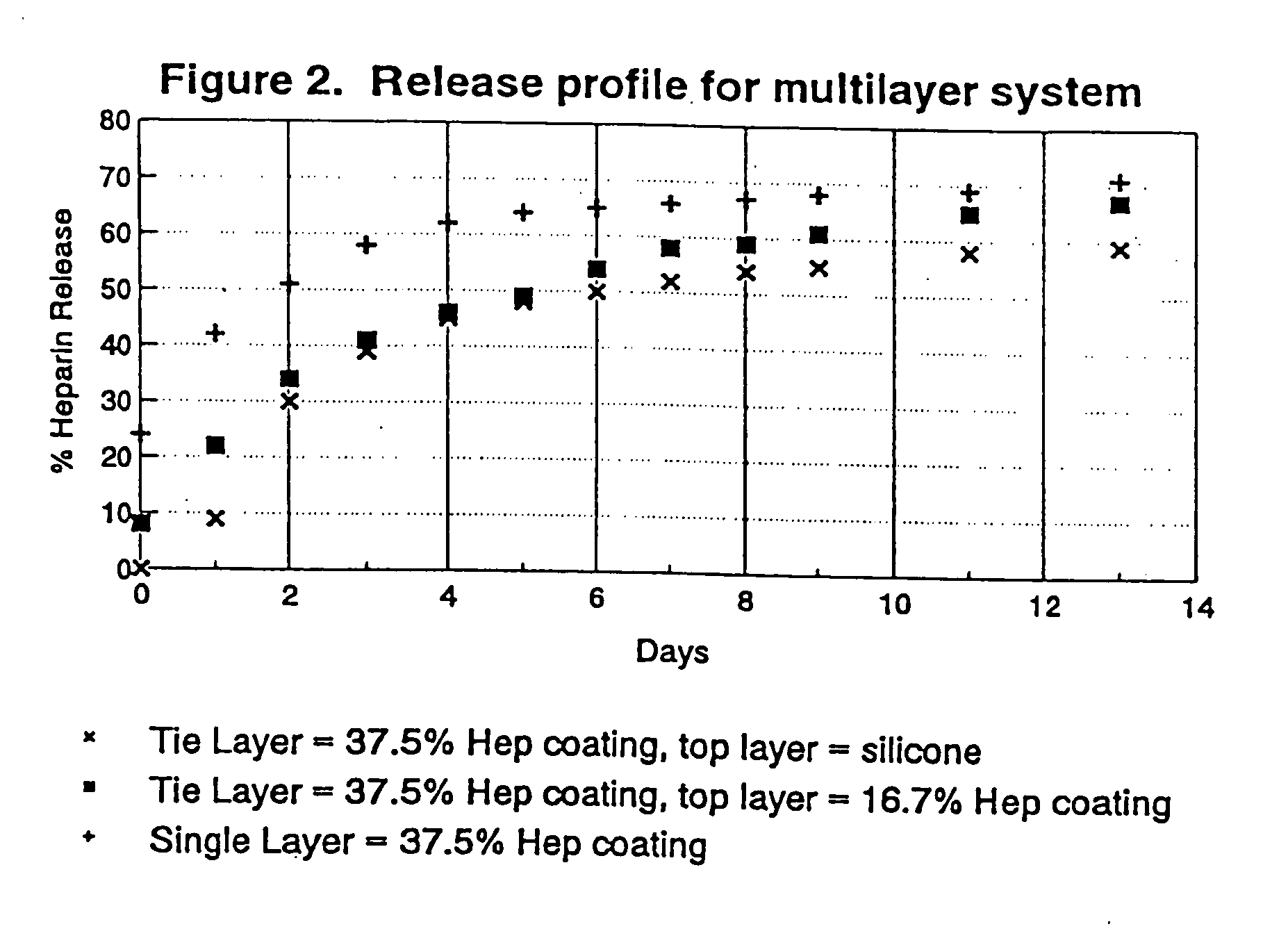
[0051] The desired release rate profile can be tailored by varying the coating thickness, the radial distribution (layer to layer) of bioactive materials, the mixing method, the amount of bioactive material, the combination of different matrix polymer materials at different layers, and the crosslink density of the polymeric material. The crosslink density is related to the amount of crosslinking which takes place and also the relative tightness of the matrix created by the particular crosslinking agent used. This, during the curing process, determines the amount of crosslinking and so the crosslink density of the polymer material. For bioactive materials released from the crosslinked matrix, such as heparin, a denser crosslink structure will result in a longer release time and reduced burst effect.
[0052] It will also be appreciated that an unmedicated silicone thin top layer provides some advantage and additional control over drug elution.

Problems solved by technology

Moreover, drug elution rates for a coating containing a hydrophilic or a lipophobic drug is usually very fast initially when the coated device contacts body fluid or blood.
Even though the method might be quite successful to control the drug release, it increases the coating thickness, reduces the effective drug loading and introduces undesirable additional foreign materials into the patient.
With regard to stents, polymeric stents, although effective, may have mechanical properties that are inferior to those of metal stents of like thickness and weave.
A polymer material of comparable strength requires a much thicker-walled structure or heavier, denser filament weave, which in turn, reduces the cross-sectional area available for flow through the stent and / or reduces the relative amount of open space in the weave.
Also, it is usually more difficult to load and deliver polymeric stents using catheter delivery systems.

Method used


Image

  • Drug coating with topcoat
  • Drug coating with topcoat
  • Drug coating with topcoat

Examples


example 1

Fluorosilicone Surface Treatment of Eluting Heparin Coating

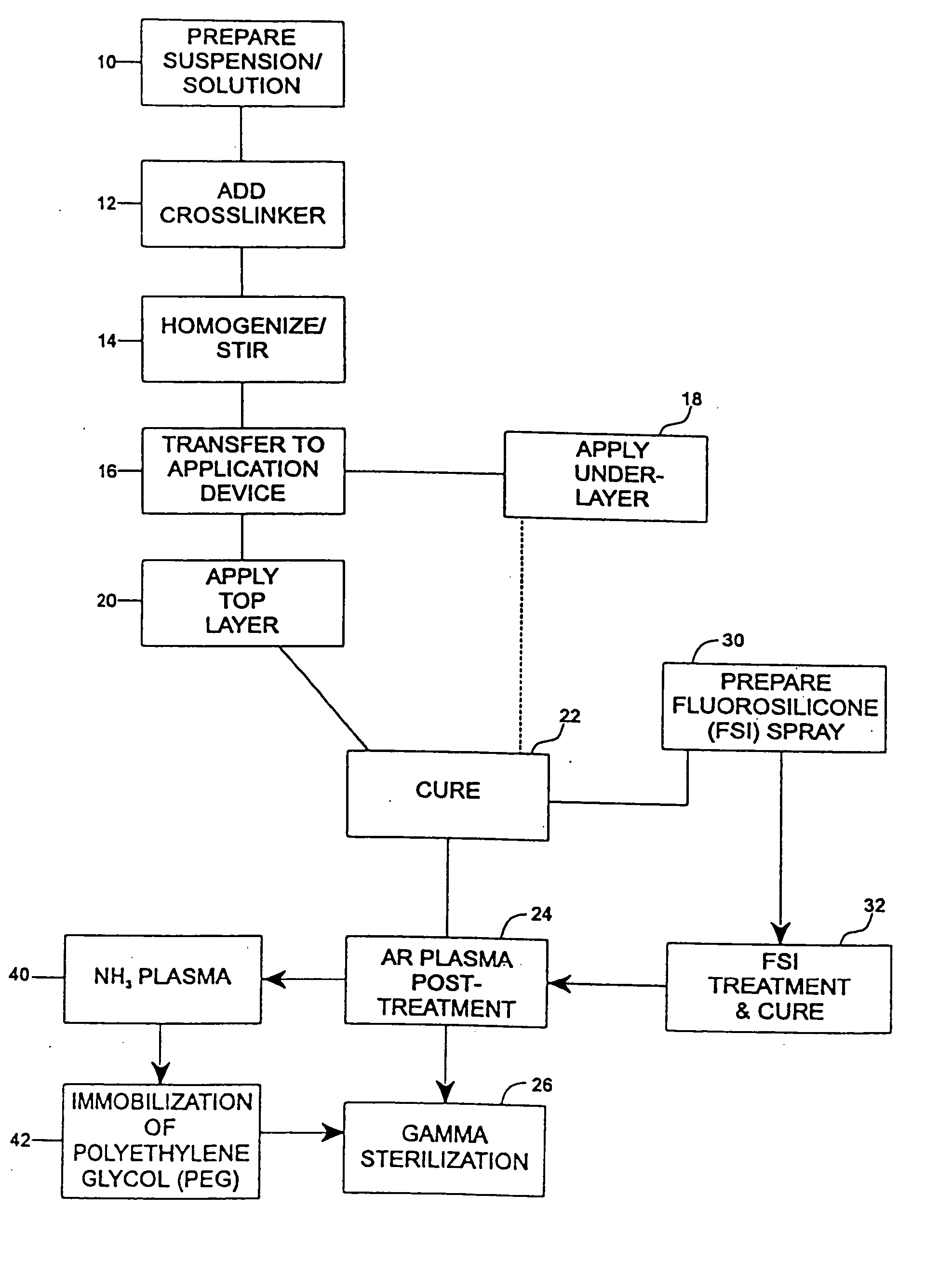
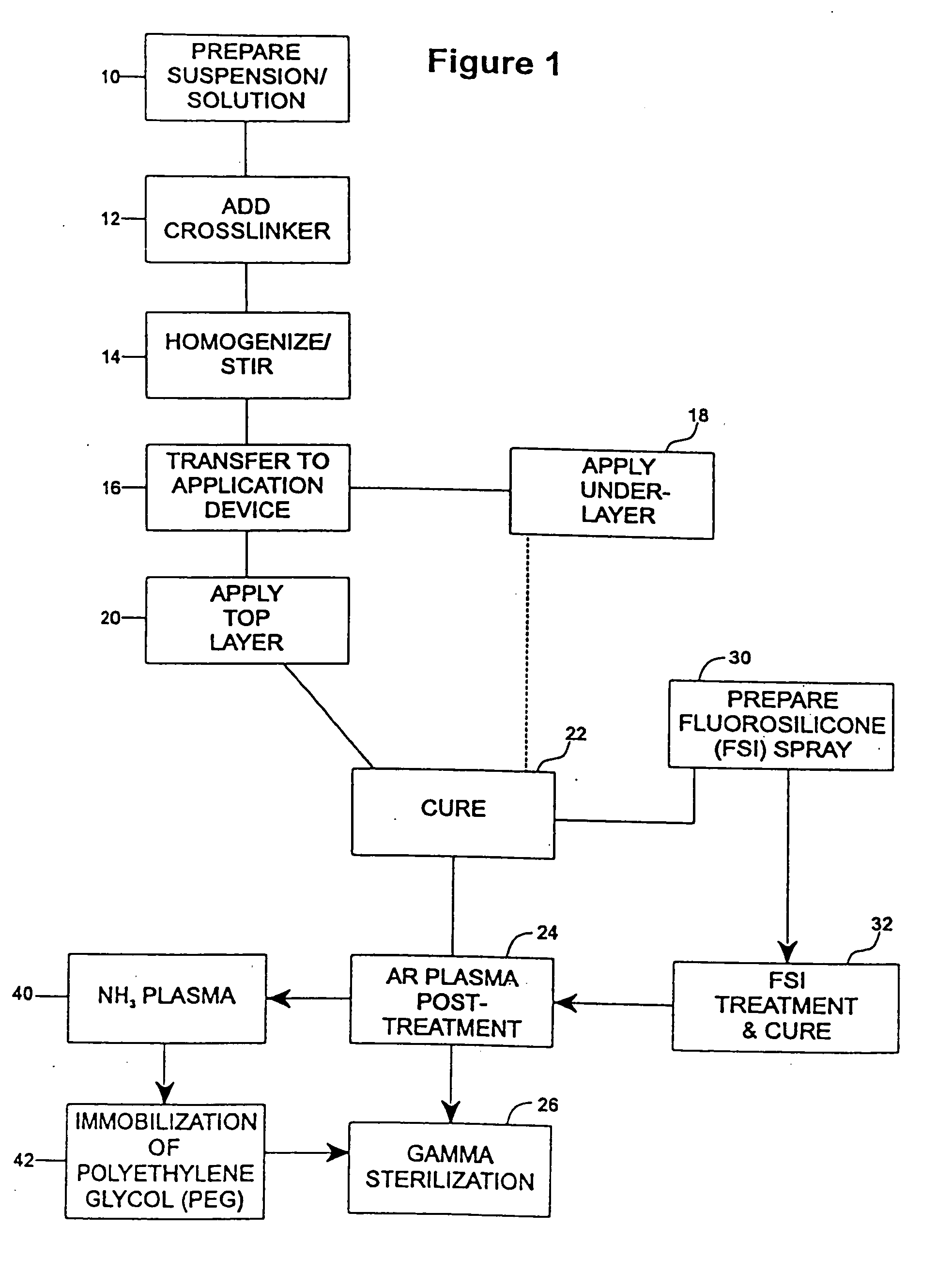
[0077] The undercoat of a stent was coated as multiple applied layers as described above thereafter and cured as described at 22. The heparin content of the undercoat was 37.5% and the coating thickness was about 30-40μ. Fluorosilicone (FSi) spray solution was prepared at 30 from a fluorosilicone suspension (Applied Silicone #40032) by weighing an amount of fluorosilicone suspension and adding tetrahydrofuran (THF) according to the relation equation of VTHF=1.2× the weight of fluorosilicone suspension. The solution was stirred very well and spray-coated on the stent at 32 using the technique of the application of the undercoat process at 18 and the coated stents were cured at 90° C. for 16 hours. The coated stents are argon plasma treated prior to gamma sterilization according to the procedures described above in accordance with steps 22-26.

[0078]FIG. 7 is a plot of heparin release kinetics in phosphate buffer system with ...

example 2

Immobilization of Polyethylene Glycol (PEG) on Drug Eluting Undercoat

[0080] An undercoat was coated on a stent and cured at 22 as in Example 1. The stent was then treated by argon gas plasma as at 24 and ammonium gas plasma at 40. The equipment and the process of argon gas plasma treatment was as has been described above. The ammonium plasma treatment was implemented immediately after the argon gas plasma treatment, to aminate the surface of the coating. The ammonium flow rate was in the range of 100-700 cubic centimeter per minute (ccM) in preferably in the range of 500-600 ccM. The power output of radio frequency plasma was in the range of 50-500 watts, preferably in ˜200 watts. The process time was in the range of 30 sec-10 min, preferably ˜5 min.

[0081] Immediately after amination, the stents were immersed into electrophilically activated polyethylene glycol (PEG) solution it 42. PEG is known to be an inhibitor of protein absorption. Examples of electrophilically activated PEG ...


PUM

PropertyMeasurementUnit
thicknessaaaaaaaaaa
thicknessaaaaaaaaaa
timeaaaaaaaaaa

Abstract

A coating and method for a coating an implantable device or prostheses are disclosed. The coating includes an undercoat of polymeric material containing an amount of biologically active material, particularly heparin, dispersed therein. The coating further includes a topcoat which covers less than the entire surface of the undercoat and wherein the topcoat comprises a polymeric material substantially free of pores and porosigens. The polymeric material of the topcoat can be a biostable, biocompatible material which provides long term non-thrombogenicity to the device portion during and after release of the biologically active material.

Description

CROSS-REFERENCE TO RELATED APPLICATIONS [0001] The present application is a Continuation-In-Part of co-pending application Ser. No. 08 / 633,518, filed Jun. 13, 1996.BACKGROUND OF THE INVENTION [0002] 1. Field of the Invention [0003] The present invention relates generally to providing biostable elastomeric coatings on the surfaces of implants which incorporate biologically active species having controlled release characteristics in the coating and relates particularly to providing a non-thrombogenic surface during and after timed release of the biologically active species. The invention is particularly described in terms of coatings on therapeutic expandable stent prostheses for implantation in body lumens, e.g., vascular implantation. [0004] 2. Related Art [0005] In surgical or other related invasive procedures, the insertion and expansion of stent devices in blood vessels, urinary tracts or other locations difficult to otherwise access for the purpose of preventing restenosis, prov...

Claims


Application Information

Patent Timeline
Patent Type & Authority Applications(United States)
IPC IPC(8): A61F2/00A61F2/82A61F2/86A61F2/90A61K9/00A61K47/32A61K47/34A61L27/00A61L27/22A61L31/08A61L31/10A61L31/14A61L31/16A61L33/00A61L33/10A61M37/00
CPCA61F2/82A61F2/86A61L2420/08A61L2300/608A61L2300/606A61L2300/602A61L2300/42A61L2300/416A61L2300/406A61L2300/236A61L33/0011A61L31/16A61L31/141A61L31/10A61L31/08A61L27/227A61F2/90A61F2210/0014A61F2250/0067C08L83/08C08L71/02C08L5/00C08L83/00C08L83/04
Inventor DING, NIHELMUS, MICHAEL N.
Owner BOSTON SCI SCIMED INC
Learn More