
Electronic controls for pollutant removal

a pollutant and electronic control technology, applied in the direction of ratio control, fluid pressure control, metal/metal-oxide/metal-hydroxide catalyst, etc., can solve the problems of increasing regulatory requirements, few can remove both types of pollutants simultaneously in a dry process or reliably achieve cost-effective levels of reduction

Inactive Publication Date: 2005-10-27
ENVIROSCRUB TECH CORP
View PDF99 Cites 42 Cited by
  • Summary
  • Abstract
  • Description
  • Claims
  • Application Information

AI Technical Summary

Benefits of technology

[0037] In another embodiment a computer system having a graphical user interface including a display and a selection device utilizes a method of providing and selecting from a menu on the display. The method may include the steps of receiving a menu entry selection signal indicative of a control operation of a portion of a pollutant removal system from a plurality of control operations including bag house control, emissions control and temperature control of the pollutant removal system and in response to the menu entry selection, retrieving a graphical representation of the selected control operation, the graphical representation having real time data fields that are populated with real time data as well as user adjustable variables. The method may further include the steps of displaying the graphical representation with the populated real time data fields on a display, receiving a signal indicative of a particular user adjustable variable and, in response to the signal, updating the graphical representation of the selected control operation to reflect the particular user adjustable variable.
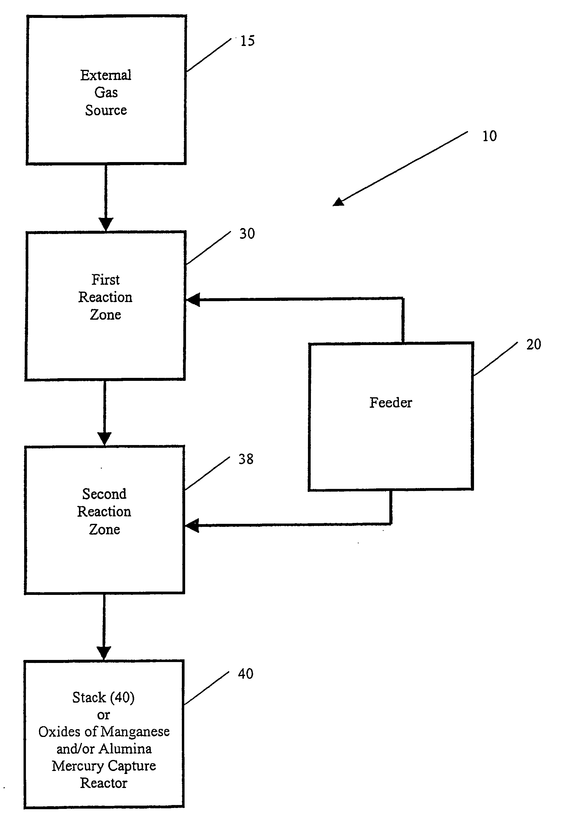
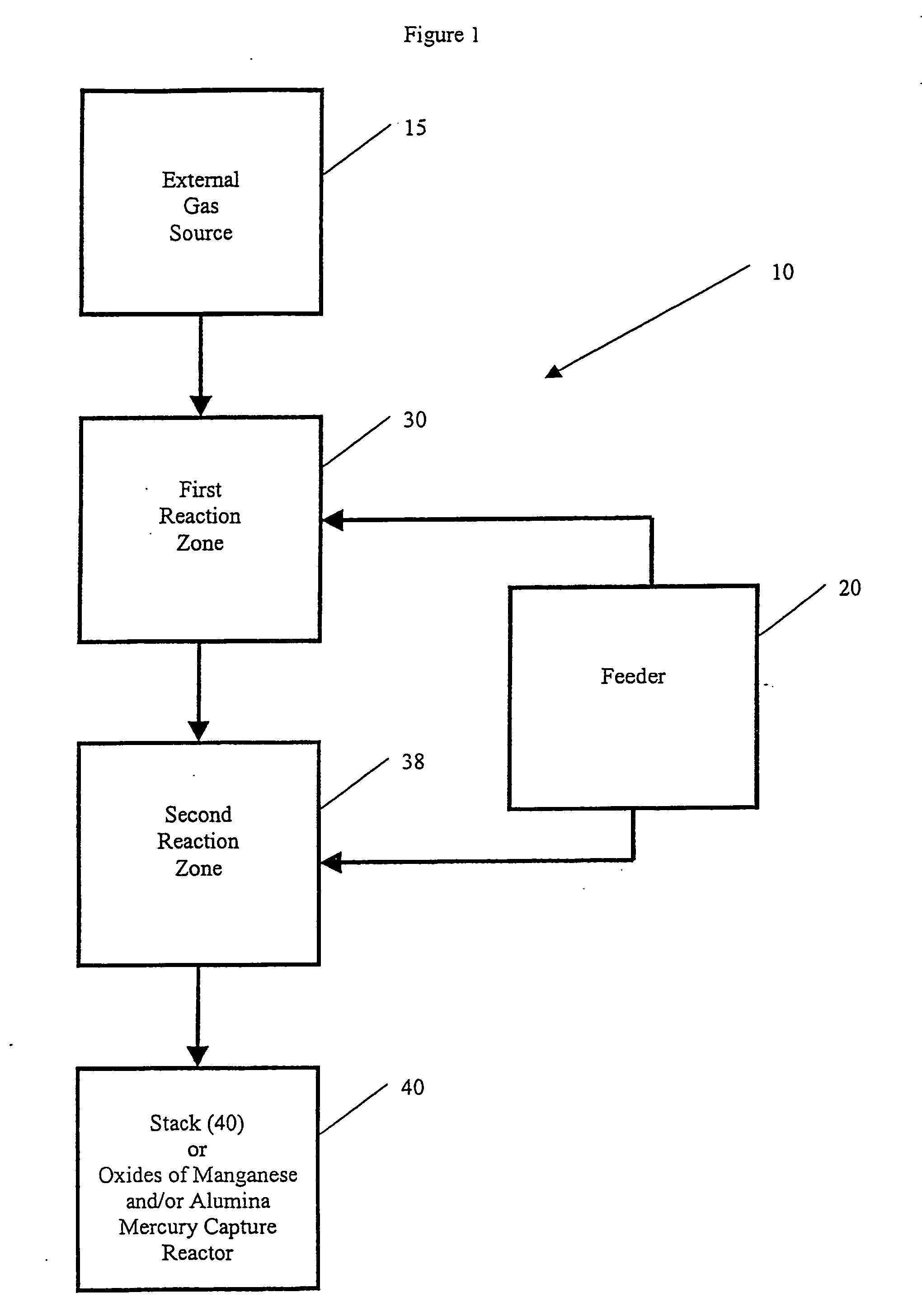
[0038] In yet another embodiment, the invention includes an electronic control system for controlling an operation of a pollutant removal system, the electronic control system having a controller operatively coupled to a first reaction zone in which at least a first target pollutant is removed from gases, the controller being configured to receive a first input from a sensor measuring at least a first target pollutant concentration at an output of the first reaction zone and determining if the measured first target pollutant concentration is within an acceptable range. The controller may be operatively coupled to a second reaction zone in which at least a second target pollutant is removed from the gases, the controller being configured to receive a second input from a sensor measuring at least a second target pollutant concentration at an output of the second reaction zone and determining if the measure second target pollutant concentration is within an acceptable range.

Problems solved by technology

The regulations are becoming more stringent and plant operators are facing greater difficulties in meeting the regulatory requirements.
Many technologies have been developed for reduction of SOX and NOX, but few can remove both types of pollutants simultaneously in a dry process or reliably achieve cost effective levels of reduction.
This in turn decreases the amount of NOX produced and therefore emitted; however, low temperature combustion does not utilize the full heating value of the coal, resulting in loss of efficiency.
With lower temperatures the full combustion / heating value of natural gas is not realized, resulting in loss of efficiency.
Unfortunately for these operators, newer environmental regulation will require even greater reduction of SOX and NOX emissions necessitating newer or more effective removal technologies and / or further reductions in efficiency.
Operators of older coal-burning power plants are often running out of space to dispose of solid wastes associated with use of scrubbers that use calcium compounds to form gypsum.
Thus, plants that currently meet the requirements for SOX emissions are facing stricter requirements for reduction of NOX for which there has been little or no economically feasible technology available.
The relatively inert nitric oxide is often only removed with great difficulty relative to NO2.
Power plant emissions represent an especially formidable source of nitrogen oxides and sulfur oxides, by virtue of the very large tonnage of these pollutants and such emissions discharged into the atmosphere annually.
Moreover, because of the low concentration of the pollutants in such emissions, typically 500 ppm or less for nitrogen oxides and 3,000 ppm or less for sulfur dioxide, their removal is difficult because very large volumes of gas must be treated.
Various methods have been proposed for the removal of sulfur dioxide from power plant flue gases, but they too have disadvantages.
However, the results of such attempts have been less successful than staged combustion.
Many fuels, and particularly those normally solid fuels such as coal, lignite, etc., also contain substantial amounts of bound or fuel sulfur with the result that conventional combustion produces substantial amounts of SOX pollutants which are also subject to pollution control.
However, it has been found that little or no reduction in SOX emissions can be obtained in a two-stage, rich-lean combustion process.
Indeed, it has been found that the presence of substantial amounts of sulfur in a fuel also has a detrimental effect on NOX reduction in a two-stage, rich-lean process.
Considerable effort has been expended to remove sulfur from normally solid fuels, such as coal, lignite, etc.
However, such systems are capital intensive and the disposal of wet sulfite sludge, which is produced as a result of such scrubbing techniques, is also a problem.
Cost inefficiencies result from the often-large differential pressures across a wet scrubber removal system; differential pressures in excess of 30 inches of water column (WC) are not unusual.
Also, the flue gases must be reheated after scrubbing in order to send them up the stack, thus reducing the efficiency of the system.
The usual scavengers in this type of operation include limestone (calcium carbonate) and dolomite (magnesium-calcium carbonate) because of availability and cost.
However, the burning techniques are complex and expensive to operate and control; and the burner equipment is comparatively expensive.
Essentially, all of the above techniques create solid waste disposal problems.
The solids or particulates, including fly ash, collected at the bag house and the spent activated carbon removed from the bed of activated carbon, all contain mercury compounds and thus pose special problems with respect to burial at landfills where strictly localized containment of the mercury compounds is imperative.
Moreover, with respect to activated carbon, that material is relatively expensive, and once spent activated carbon particles are removed from an adsorbent bed, they cannot be easily regenerated and used again.
However, such processes do not capture SOX and NOX.
Some of the known methods of bringing oxides of manganese in contact with a gas stream, i.e., sprayed slurries, beds of manganese ore or special filters, have been cumbersome.
Although the prior art teaches the use of oxides of manganese to remove SOX and / or NOX, they do not teach an adaptable system or process that can capture SOX and / or NOX and other pollutants with oxides of manganese and monitor and adjust system operational parameters, such as differential pressure, to provide real-time system control.
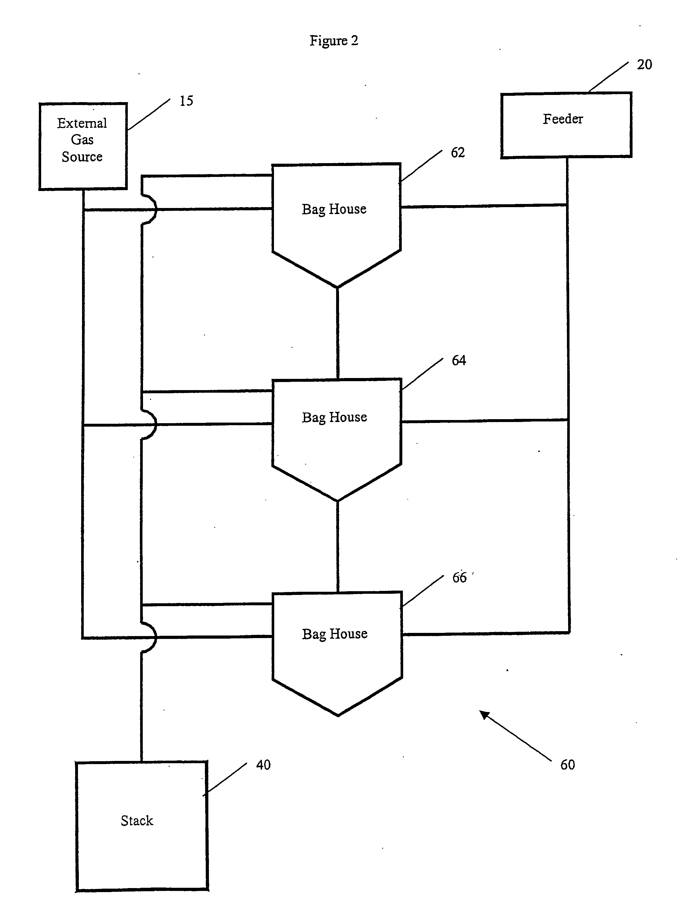
Although these prior art discloses and teach the use of bag houses for removal of particulates and as a reaction chamber, they do not teach the use of bag houses in an adaptable system capable of monitoring and adjusting system operational parameters, such as differential pressure, to capture SOX and / or NOX and other pollutants with oxides of manganese.
Wet removal processes can result in significant differential pressures across a removal system.
Such large differential pressures are costly because significant energy must be expended to counter the differential pressure and provide a waste gas stream with sufficient energy to flow up and out of a stack.
They are purchased and consumed in significant quantities and once gypsum is formed the calcium compounds cannot be recovered, at least not cost-effectively.

Method used


Image

  • Electronic controls for pollutant removal
  • Electronic controls for pollutant removal
  • Electronic controls for pollutant removal

Examples


example 1

[0162] NOX concentrations were determined using EPA method 7E, chemiluminesent analysis method, and analyzed with a model 42H chemiluminescent instrument manufactured by Thermo Electron Inc. Sulfur dioxide (SO2) concentrations were measured utilizing, a spectrophotometric analysis method employing a Bovar Western Research Spectrophotometric model 921NMP instrument. In order to obtain accurate and reliable emission concentrations, sampling and reporting was conducted in accordance with US EPA Reference CFR 40, Part 60, Appendix A, Method 6C. Gas flow rates in standard cubic feet per minute (scfm) were measured using AGA method #3, utilizing a standard orifice plate meter run. The demonstration was conducted utilizing a series of test runs on live gas streams from a power plant. Said power plant operates steam boilers which are fired on high sulfur coal. During test runs, NOX and SO2 concentration readings were taken continuously alternating from the inlet and the outlet of the demons...

example 2

[0163] A test using the demonstration unit according to the invention, utilizing oxides of manganese as the sorbent was conducted on a simulated gas stream containing varying levels of NOX. Oxides of manganese powders that were used during this test described generally by 60% of particles less than 45 microns in size and having a BET surface area of approximately 30 m2 / g. Knowing that there is a competition for reaction sites between SO2 and NOX, a series of tests was conducted to gather data on the efficiency of NOX capture in the absence of SO2. Synthetic NOX gas was made on site by use of high-concentration bottle gas which was diluted into the inlet gas stream and processed by the demonstration unit. The bag house was pre-loaded with oxides of manganese prior to introduction of test gas by operating the demonstration unit's blower at high speed (typically about 1200 scfm), and feeding the oxides of manganese into the gas stream at a high rate (between 40% and 90% of feeder capac...

example 3

[0165] A further test of the demonstration unit according to the invention utilizing oxides of manganese as the sorbent, was conducted on a live exhaust gas slipstream from a 170 MW coal fired boiler. The boiler was operating on high sulfur coal of approximately 4-6% sulfur, resulting in emission concentrations of SO2 in the range of 1200-2000 ppm and NOX concentrations in the range of 280-320 ppm. A slipstream averaging 1000 scfm was diverted from the main stack exhaust and routed to the demonstration unit for reaction and sorption by the sorbent oxides of manganese. SO2 and NOX concentrations were measured at the scrubber inlet and outlet of the bag house on an alternating basis throughout the testing with the demonstration unit's continuous emissions monitoring system (CEMS). SO2 concentrations were measured utilizing a Bovar Western Research model 921NMP spectrophotometric analyzer and NOX concentrations were measured utilizing a Thermo Electron model 42H chemiluminescent instru...


PUM

PropertyMeasurementUnit
weightsaaaaaaaaaa
particle sizeaaaaaaaaaa

Abstract

An electronic control system for regulating operational parameters in a pollution removal system. The pollution removal system may contain at least one reaction zone connected to a source of gas and a sorbent feeder containing a supply of sorbent. The system may include a pollutant concentration sensor that measures the concentration of at least one target pollutant in a gas exiting a reaction zone, a differential pressure sensor that measures the differential pressure across a reaction zone, a sorbent feed rate controller that regulates sorbent feed rate to the reaction zone, and a controller in communication with these elements. The controller may use the measured values to adjust sorbent feeder rate to ensure that the target pollutant concentration in a gas exiting the reaction zone is within an acceptable range and that differential pressure across the reaction zone is no greater than a predetermined level.

Description

RELATED APPLICATIONS [0001] This application is a continuation of U.S. Utility application Ser. No. 10 / 382,348 filed Mar. 4, 2003, which was a continuation of U.S. Utility application Ser. No. 09 / 919,600, filed Jul. 31, 2001, now issued as U.S. Pat. No. 6,610,263. This application claims priority to the following US Provisional Applications: No. 60 / 222,236, filed Aug. 1, 2000; Nos. 60 / 232,049; 60 / 232,097, both filed Sep. 12, 2000; No. 60 / 238,105, filed Oct. 4, 2000; Nos. 60 / 239,422; 60 / 239,435, both filed Oct. 10, 2000; No. 60 / 242,830, filed Oct. 23, 2000; No. 60 / 243,090, filed Oct. 24, 2000; No. 60 / 244,948, filed Nov. 1, 2000; Nos. 60 / 288,166; 60 / 288,165; 60 / 288,237; 60 / 288,245; 60 / 288,243; 60 / 288,242; 60 / 288,168; 60 / 288,167, all filed May 2, 2001; Nos. 60 / 295,930; 60 / 296,006; 60 / 296,005; 60 / 296,004; 60 / 296,007; 60 / 296,003; all filed Jun. 5, 2001; and Nos. 60 / 299,362; 60 / 299,363, both filed Jun. 19, 2001, all of which are incorporated herein by reference.FIELD OF THE INVENTION [000...

Claims


Application Information

Patent Timeline
Patent Type & Authority Applications(United States)
IPC IPC(8): B01D50/00B01D53/04B01D53/06B01D53/30B01D53/34B01D53/50B01D53/56B01D53/60B01D53/64B01D53/83B01D53/86B01J23/34B01J23/92B01J35/02B32B27/02C01B21/00C22B7/00C22B7/02C22B43/00F01N3/00F23J11/00F23J15/00F23J15/02G05D7/06G05D16/20G05D21/02G05D23/19
CPCC22B7/006Y10S423/05C22B43/00F23J15/006F23J15/02F23J2215/10F23J2215/20F23J2215/60F23J2217/101F23J2219/60G05D7/0635G05D16/2013G05D21/02G05D23/1917Y02C20/10B01D53/04B01D53/0423B01D53/0446B01D53/0454B01D53/06B01D53/08B01D53/12B01D53/30B01D53/346B01D53/508B01D53/565B01D53/60B01D53/64B01D53/83B01D53/8609B01D53/8628B01D53/8665B01D2253/10B01D2253/112B01D2253/304B01D2253/306B01D2257/302B01D2257/304B01D2257/404B01D2257/602B01D2258/00B01D2259/40B01D2259/41B01J23/34B01J23/92B01J35/023C22B7/02Y02P10/146G05D16/028Y02P10/122Y02P10/20B01J35/40
Inventor HAMMEL, CHARLES F.
Owner ENVIROSCRUB TECH CORP
Learn More