[0009] In accordance with the present invention, cavity lasers exhibit a relatively high beam quality (e.g., M2<1.25) despite a relatively small cavity length (e.g., 50-53 mm) for a high (e.g., ≧10
watt) output power device. This enables the construction of physically smaller laser and optical assemblies without sacrificing performance. The present invention also facilitates reduction of optical photonic interference, which can impair imaging performance. In one illustrative embodiment, laser and optical assemblies utilize an aperture defined within an
optical barrier element to reduce the
divergence of the
light beam emanating from a
diode-pumping laser. This
divergence-reduced light beam is further focused onto a “host” laser
crystal (e.g., Nd:YVO4, Nd:GdVO4, Nd:YLF, Nd:YAG) with a relatively reduced
dopant level (e.g., about 0.2-0.5%) so as to reduce the amount of bulk tensing occurring therein. This reduced
doping level allows the absorption of the pump energy to take place over a longer length of the
crystal, resulting in a more uniform
crystal heating. The size of the aperture, coupled with the reduced crystal
doping level reduces the effective aperture of the host crystal; this facilitates use of an
output coupler / Lens with a greater-than-normal curvature, which, in turn, reduces the length of the laser cavity. Moreover, the length of the crystal may be reduced (e.g., from 12 mm to 10 mm) so that the characteristics of the light beam illuminating a recording medium can be controlled by selecting a particular
output coupler rather than a particular crystal. A second aperture is desirably disposed between the crystal and the
output coupler to reduce the amount of cavity
noise and to improve the mode quality (e.g., M2).
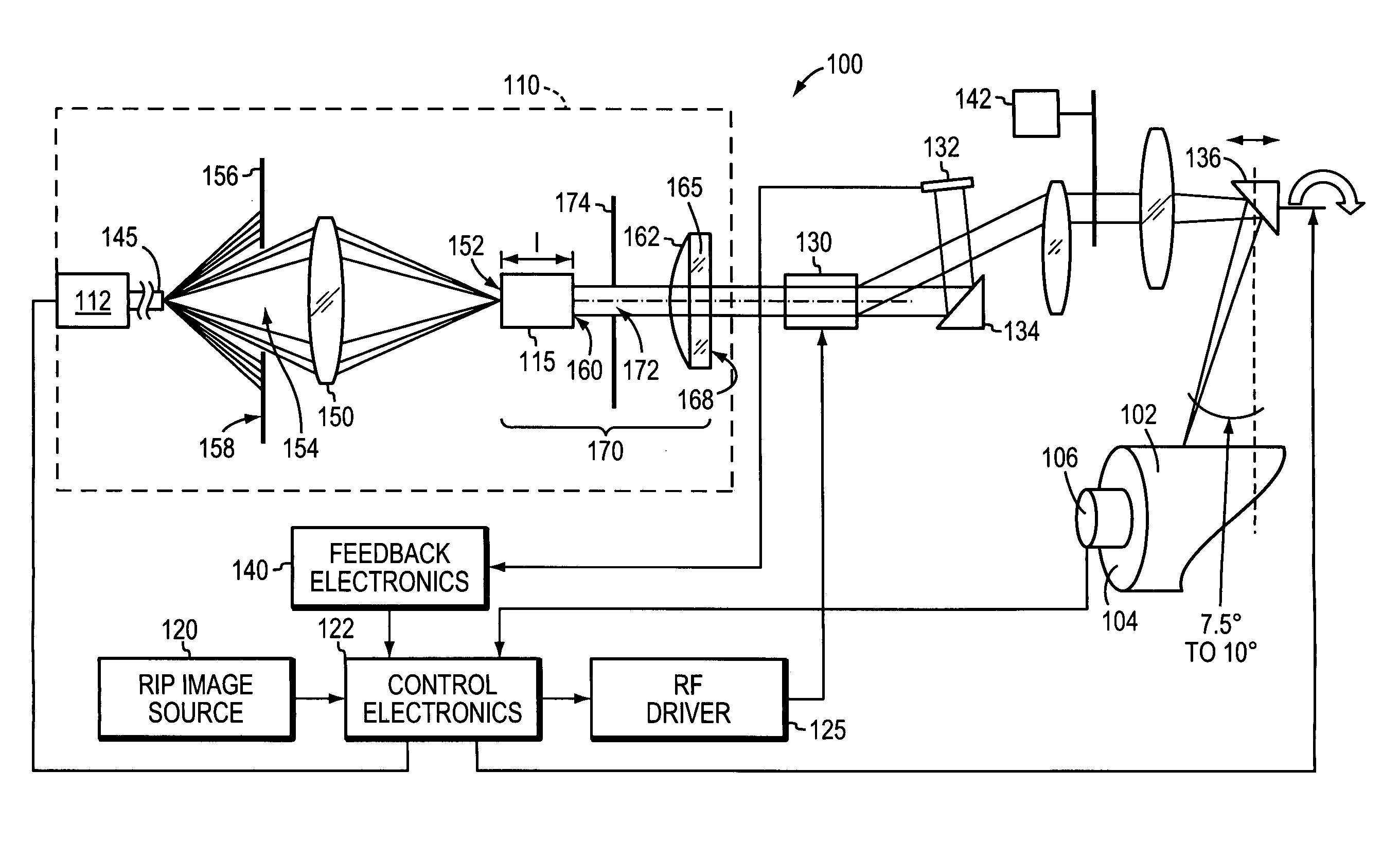
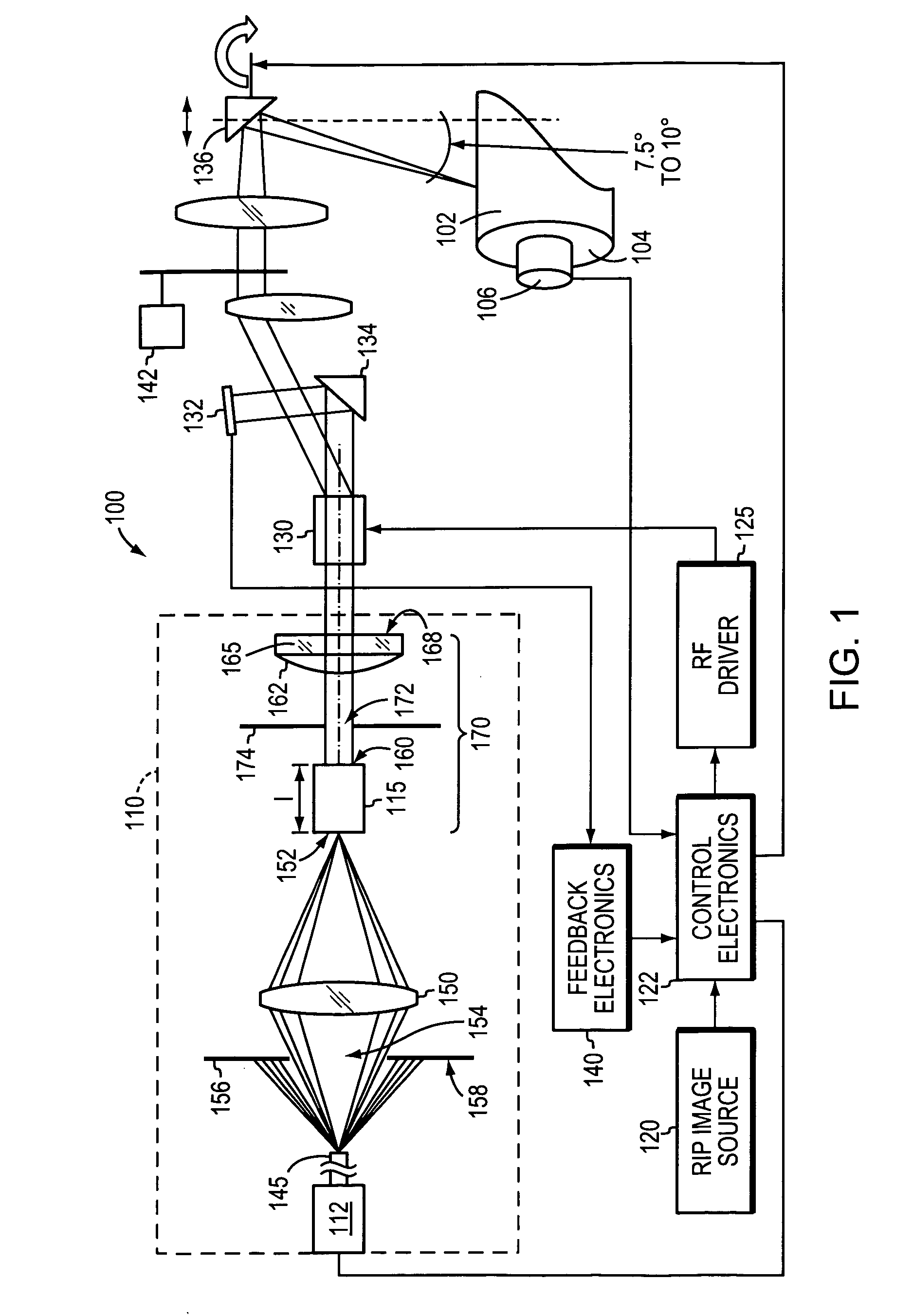
[0010] When used in recording systems, the light beam emanating from the laser
system may be directed at a recording medium in accordance with a predetermined
angle of incidence—rather than striking the recording medium perpendicularly—to reduce the amount of back-reflections (which may damage the laser and / or result in undesirable over- or under-exposures of the recording medium) and / or other undesirable interferences (e.g., ionized
gas plasma and debris plumes caused by
thermal decomposition within the recording medium) that may adversely affect the operation of the laser and reduce the desired
image quality. In one particularly advantageous embodiment, the light beam emanating from the laser
system onto the recording medium exhibits an incidence angle in the range of about 7.5° to about 10.0° (for
infrared (IR) or near-IR wavelengths; this range may vary for
ultraviolet or other wavelengths), rather than a more conventional 2° incidence angle. The relatively larger incidence angle protects the laser from undesirable back-reflections, as well as reducing the effects of plume and
plasma interference with the beam; it also improves
image quality and reduces the requisite imaging power and resulting emissions. As will become apparent to those skilled in the art,
plasma / plume shielding using a relatively large incidence angle can be beneficially applied in a wide variety of implementations, such as laser marking,
laser engraving,
laser milling, etc.
[0011] The use of large offset angles is contrary to standard practice. For example, in systems that position the laser beam using a
spinning mirror, an increase in offset angle increases the overall width of an internal cylinder imager by the distance from the center of the
spinning mirror to the point where the beam hits the cylinder (i.e., distance multiplied by the angle tangent), and distorts the optical spot so it is no longer round. Moreover, larger incidence angles reduce the energy absorbed into the
layers of a recording medium, e.g., by increasing reflected energy. For these reasons, the offset angle is typically minimized. It has been found, however, in accordance with the present technology, that the unexpected benefits outweigh the conventional disadvantages.
[0013] In accordance with at least some aspects of the disclosed technology, the output of the pumping source is provided to the
Laser crystal via an optical
assembly that includes a focusing lens arrangement and a
beam divergence-reducing aperture through an
optical barrier. The
assembly may also include a second
beam divergence-reducing aperture between the crystal and the output coupler. This second aperture reduces the pump
noise due to power supply-line variances and mode disturbances and also stabilizes the cavity. The beam emerging from the second aperture is provided to an acoustic
optical modulator (“AOM”) and then the 1st-order (and / or the 0th-order) beam, which will be deflected onto the recording medium, and the 2nd-order beam, which will be discarded, are collimated. The AOM modulates the beam to produce “dot-on-demand” imaging on the printing medium, causing the beam to strike the printing medium only where dots are required in accordance with image data. Placement of the beam on the printing medium is accomplished by a polygonal mirror rotating at a fixed speed based on the imaging resolution.
[0014] In
ablation-type systems, the beam is focused on the “
ablation layer” of the recording material, which is designed to volatilize in response to laser
radiation. In transfer-type systems, the beam is focused on the transfer layer. In either case, the
depth of focus of the laser beam provides a degree of tolerable deviation. The
depth of focus, in turn, is enhanced by using a single-mode laser beam of high quality (i.e., low M2). Accordingly,
depth of focus is important in commercial plate-imaging systems, and the present invention provides the necessary depth of focus and beam quality in a small laser
package.
[0019] In one embodiment of this aspect of the invention, the apparatus further includes a second optical barrier element with a second aperture defined therethrough, the aperture being positioned within the
resonator cavity to reduce
modal power disturbances and block unwanted
modes. The second aperture may exhibit a
diameter in a range of about 0.02 to 0.05 inch.

