Bi-layer HVOF coating with controlled porosity for use in thermal barrier coatings

a technology of thermal barrier coating and bi-layer hvof, which is applied in the direction of liquid fuel engine components, combination recording, record information storage, etc., can solve the problems that the state of the art of using hvof and aps to form a bi-layer bond coat with such attributes would not be considered “manufacturer friendly”, and achieves improved ductility of the bond coat, sacrificing mechanical compliance, strength or stability, and promoting roughness

Inactive Publication Date: 2005-11-24
GENERAL ELECTRIC CO
View PDF7 Cites 36 Cited by
  • Summary
  • Abstract
  • Description
  • Claims
  • Application Information

AI Technical Summary

Benefits of technology

[0016] As noted above, improved bond coatings in accordance with the invention are preferably formed by using a bi-layer bond coat applied entirely by HVOF thermal spraying. The bi-layer coating consists of a dense inner layer that provides oxidation protection of the metal substrate and an outer layer having controlled porosity that tends to promote roughness and provide improved ductility of the bond coat without sacrificing mechanical compliance, strength or stability. Surprisingly, it has been found that the second outer HVOF layer having controlled porosity can be formed by spraying a mixture of metallic powder and polyester via HVOF.
[0017] The present invention thus achieves three desirable attributes of a bond coat for use with TBC systems, namely a layer of high density material to prevent egress of oxygen to the substrate, a high degree of roughness to promote adherence with, for example, the TBC, and controlled porosity for good mechanical compliance. The current state of the art using both HVOF and APS to form a bi-layer bond coat hav...

Problems solved by technology

The current state of the art using both HVOF and APS to form a bi-layer bond coat having such attributes would not be considered “manufacturing friendly” du...

Method used


Image

  • Bi-layer HVOF coating with controlled porosity for use in thermal barrier coatings
  • Bi-layer HVOF coating with controlled porosity for use in thermal barrier coatings
  • Bi-layer HVOF coating with controlled porosity for use in thermal barrier coatings

Examples


example 1

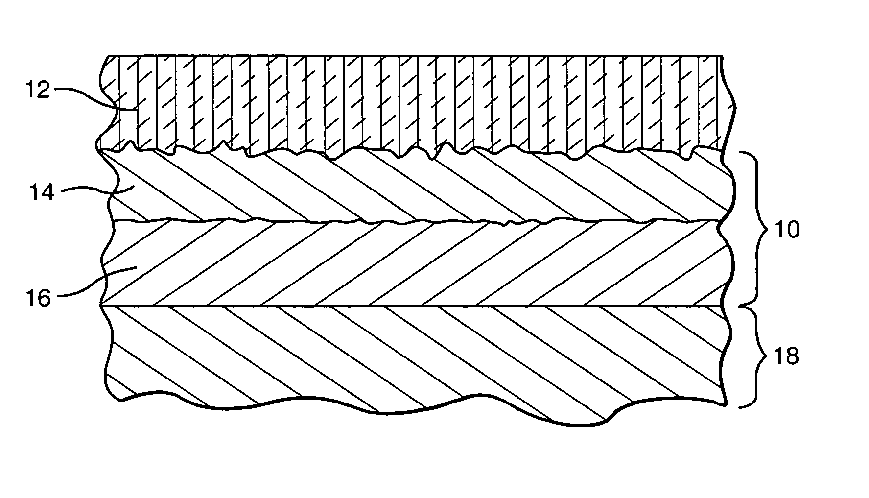
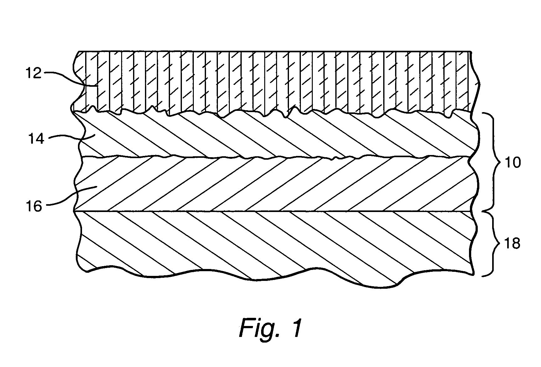
[0027] A bi-layer coating was fabricated according to the invention using JP5000 HVOF equipment manufactured by TAFA. An initial dense layer of NiCrAlY using Praxair Powder No. Ni211-17 (Bal-Ni-22-Cr-10Al-1-Y) was initially applied to an IN718 substrate (52Ni-19Fe-19Cr-5Nb-3Mo-1Ti) using HVOF.

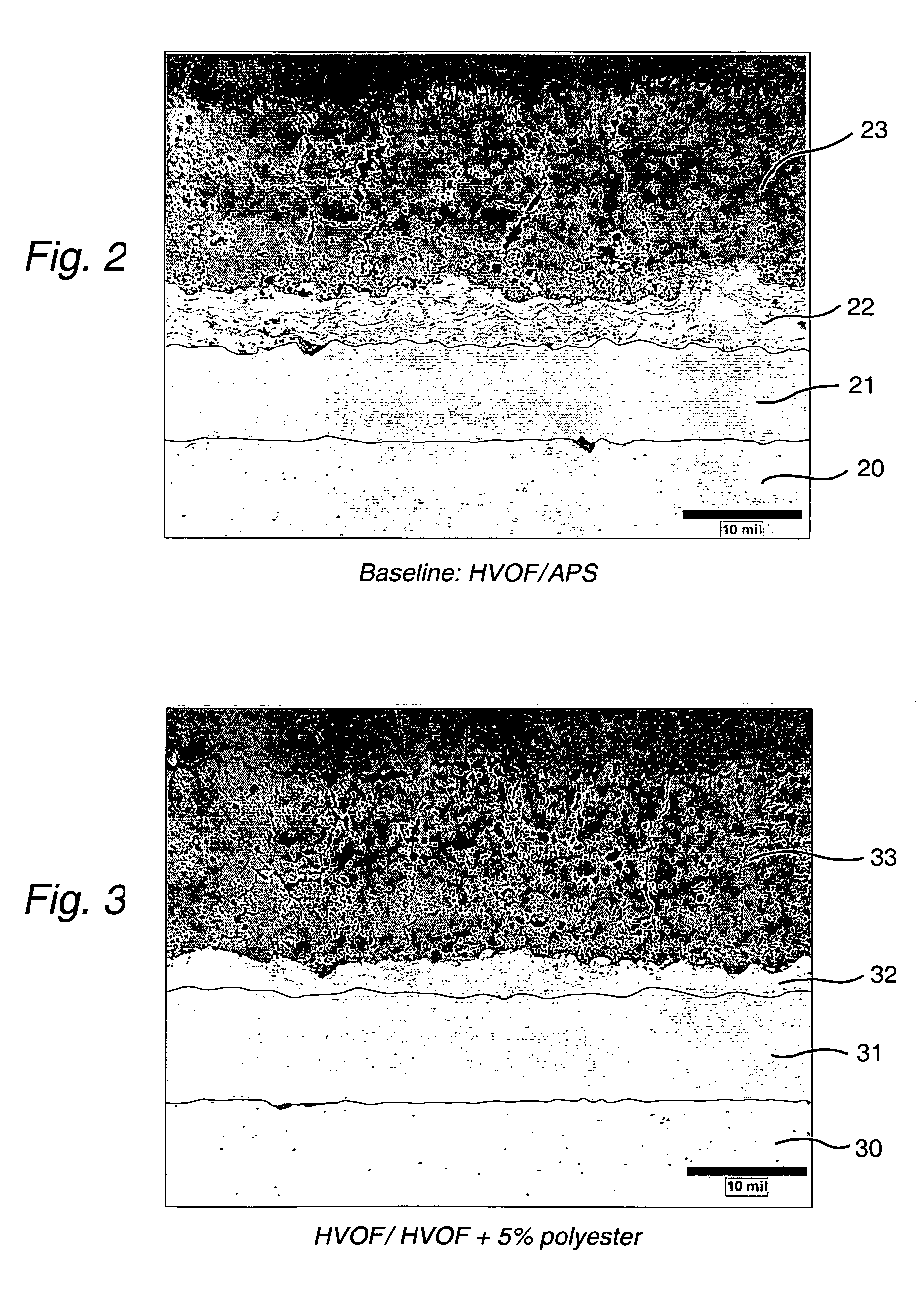
[0028] A second porous layer was then created by spraying a mixture of NiCrAlY, Ni211-17, and polyester powder, namely Metco 600NS powder. The Metco 600NS, Ni211 and IN718 are commercially available materials. After spraying the second coating using HVOF, a metallographic section was prepared and evaluated. The examination confirmed that the outer layer exhibited increased porosity as compared to the more dense inner layer. Using quantitative image analysis, the amount of porosity of the outer layer was determined to be about 3 to 4% of the total layer volume.

[0029] Follow-up experiments evaluated other ratios of NiCrAlY / polyester mixtures. Blends of 5, 9, and 15% by weight polyester were fab...


PUM

PropertyMeasurementUnit
Percent by massaaaaaaaaaa
Thicknessaaaaaaaaaa

Abstract

A bi-layer bond coating for use on metal alloy components exposed to hostile thermal and chemical environment, such as a gas turbine engine used to generate electricity and the method for applying such coatings. The preferred coatings include a bi-layer bond coat applied to the metal substrate, with both layers being applied using high velocity oxy-fuel (HVOF) thermal spraying. In one embodiment, bond coatings in accordance with the invention can be used in combination with a thermal barrier coating (“TBC”). However, the invention can also take other forms, such as a stand alone overlay coating. Bi-layer bond coatings in accordance with the invention consist of a dense first inner layer (such as iron, nickel or cobalt-based alloys) that provides oxidation protection to the metal substrate, and a second outer layer having controlled porosity that tends to promote roughness, mechanical compliance, and promotes adherence of the TBC. Preferably, the outer, less dense layer of the bi-layer bond coat is formed from a mixture of metallic powder and polyester to adjust and control the porosity, but without sacrificing mechanical compliance. Together, the layers enhance adherence to the substrate and improve the overall life of the coating system.

Description

BACKGROUND OF THE INVENTION [0001] The present invention relates to protective coatings for metal alloy components, such as the working components of gas turbine engines that are exposed to high temperature gas environments and severe operating conditions. More particularly, the invention relates to a new type of protective bond coating that includes a bi-layer bond coat applied to a metal substrate using high velocity oxy-fuel (“HVOF”) thermal spraying. In one embodiment, bond coatings in accordance with the invention can be used in combination with a thermal barrier coating (“TBC”). However, the invention can also take other forms, such as a stand alone overlay coating. [0002] Exemplary bi-layer bond coatings in accordance with the invention include a dense first inner layer that provides oxidation protection to the metal substrate, and a second outer layer having controlled porosity that tends to promote roughness and aids adherence of the TBC to the bond coat. Preferably, the se...

Claims


Application Information

Patent Timeline
IPC IPC(8): C23C4/04F01D5/28C23C4/08C23C4/12C23C28/00F02C7/00
CPCC23C4/18C23C26/00C23C28/3215C23C28/325C23C28/3455Y02T50/67Y10T428/12569Y10T428/12736Y10T428/12847Y10T428/26Y10T428/12479Y10T428/12611Y10T428/263Y10T428/31681Y02T50/60
Inventor NELSON, WARREN ARTHURSCHAEFFER, JON CONRADSWEDE, SHARON TROMBLYBUCCI, DAVID VINCENTDEBARRO, JOSEPHSTROUT, TERRY HOWARDMORTENSEN, TYRONE ROBERT
Owner GENERAL ELECTRIC CO
Why Eureka
Try Eureka