Method for purifying carbon dioxide

a carbon dioxide and purification method technology, applied in the field of purification methods, can solve the problems of difficult purification of cosub>2/sub>to a high level, inability to use products, and inability to impregnate wafers and other high-purity substrates, and achieve the effect of reducing adsorbent and sufficient purity

Active Publication Date: 2005-12-01
ENTEGRIS INC
View PDF8 Cites 43 Cited by
  • Summary
  • Abstract
  • Description
  • Claims
  • Application Information

AI Technical Summary

Benefits of technology

[0008] The invention pertains to a method for the purification of CO2 to achieve sufficient purity for its use in the semiconductor industry. The method comprises contacting the CO2 stream, gas, liquid or supercritical fluid, with a quantity of at least one mixed metal oxide wherein the mixed metal oxide comprises at least two oxidation states of one or more metals; or two metals with similar relatively high oxidation states with different chemical properties. The invention comprises the use of a single mixture of materials to achieve low levels of a number of contaminants Decontamination of the CO2 can take place in any of a number of purification apparatuses including both bed and canister apparatuses. The contaminants of primary concern are O2 water, metals, sulfurous contaminants, especially COS, phosphorus containing contaminants, silicon containing contaminants, and non-methane hydrocarbons (NMHC). Contaminants of secondary concern are nitrogenous contaminants, especially NH3 and NOx, wherein 1≦x≦2 and other inorganic compounds. Total contaminant levels are reduced to less than 100 ppb using the method of the invention.
[0009] The invention allows for removal of a broad range of contaminants from the CO2. Oxidizable contaminants are absorbed on the high oxidation state portion of the material and reducible contaminants are adsorbed on the low oxidation state portion of the material. The selection and ratios of metals is dependent upon the source of CO2 to be decontaminated in conjunction with the contaminants to be removed.
[0010] The invention further pertains to methods for the activation and regeneration of the metal oxides to provide adsorbents with multiple oxidation states to allow for sequestration of a variety of contaminants. Activation and regeneration comprise exposure of the adsorbent to oxygen at a relatively high temperature for a period of time to nearly fully oxidize the metals. The adsorbents are then cooled and exposed to a reducing agent, such as 1-5% hydrogen (H2) in an inert gas such as nitrogen (N2) or argon (Ar) for a sufficient period of time to partially reduce the adsorbent. In addition to producing a mixed metal oxide, the activation and regeneration steps purge contaminants from the adsorbents. Exact methods for activation and regeneration depend on the type of beds, the adsorbents used and the major contaminants in the CO2.

Problems solved by technology

The presence of contaminants in such ultrahigh purity applications can result in products that are unusable in the case of semiconductor applications or the damage of optics and lasers in other relevant applications.
Purification of CO2 to a high level is difficult as CO2 is inherently wet.
However, this property can also result in impregnation of wafers and other high purity substrates with contaminants present in the CO2 stream.
Additionally, the high pressure and temperature of the fluid can result in some contaminants becoming more nefarious.
For example, water and oxygen in the context of supercritical CO2 can become highly corrosive, whereby desired structural features on wafers are subject to degradation.
Leached metals are volatile at low concentrations, ppb to parts per trillion (ppt), and are readily captured in the gas phase resulting in potential contamination of silicon wafers or other high purity products.
Although the high silica zeolites are able to remove heavy hydrocarbons from CO2 efficiently, removal of other contaminants is limited.
Either arrangement results in a complex system.

Method used


Image

  • Method for purifying carbon dioxide
  • Method for purifying carbon dioxide

Examples


example

[0039] A test purifier was filled with a adsorption media containing a including a pre-oxidized mixture of Ni / NiO, approximately 60% by weight on an a silica support, exposed to air for several days. The purifier was activated for 29 hours at ambient temperature using a 5% H2 / 95% Ar purge gas at 1 standard liter / minute (slm) at 0 pounds / square inch gauge (psig). Afterwards, the purifier was purged with gaseous CO2 purified with an Aeronex SS-500-KF-A-4R purifier. The temperature was monitored to indicate when each media was finished reacting with the CO2.

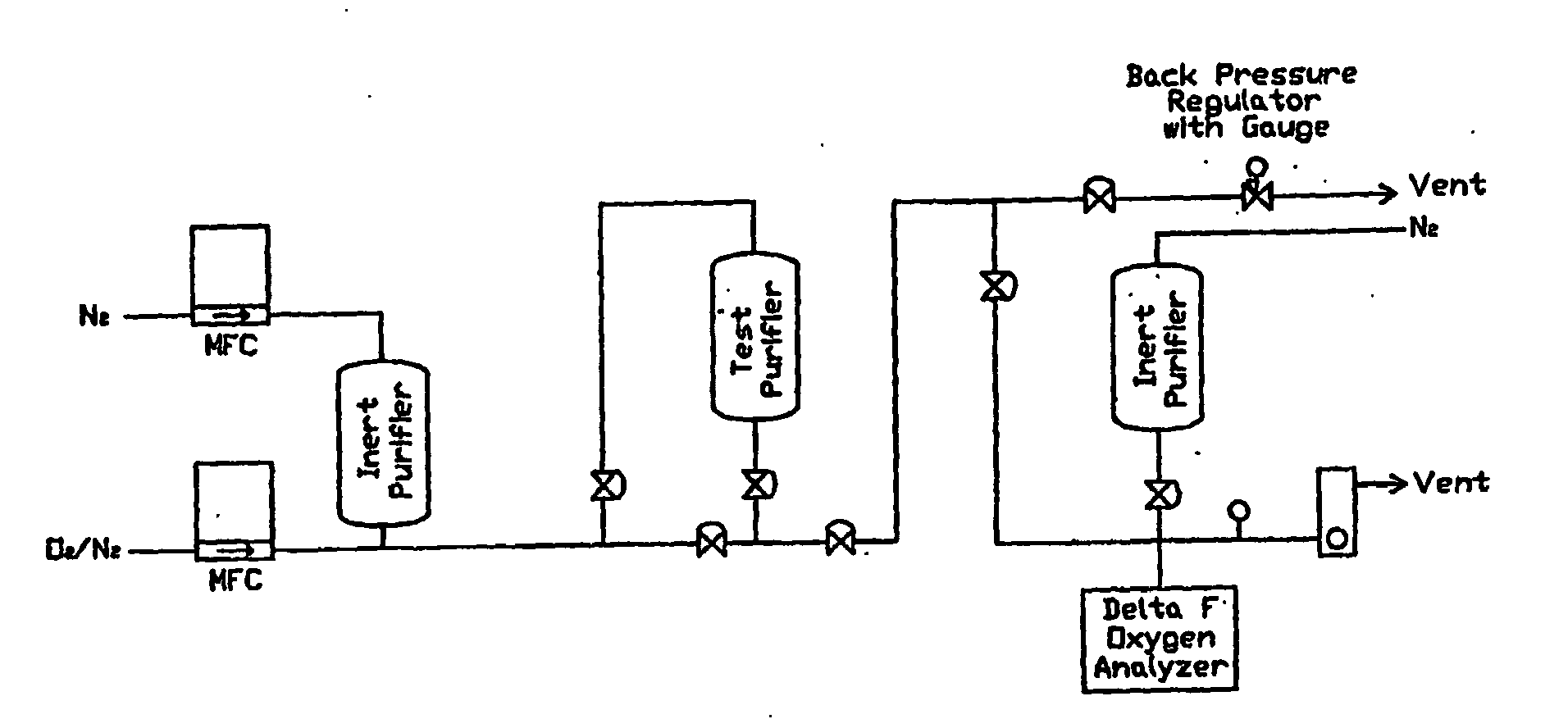
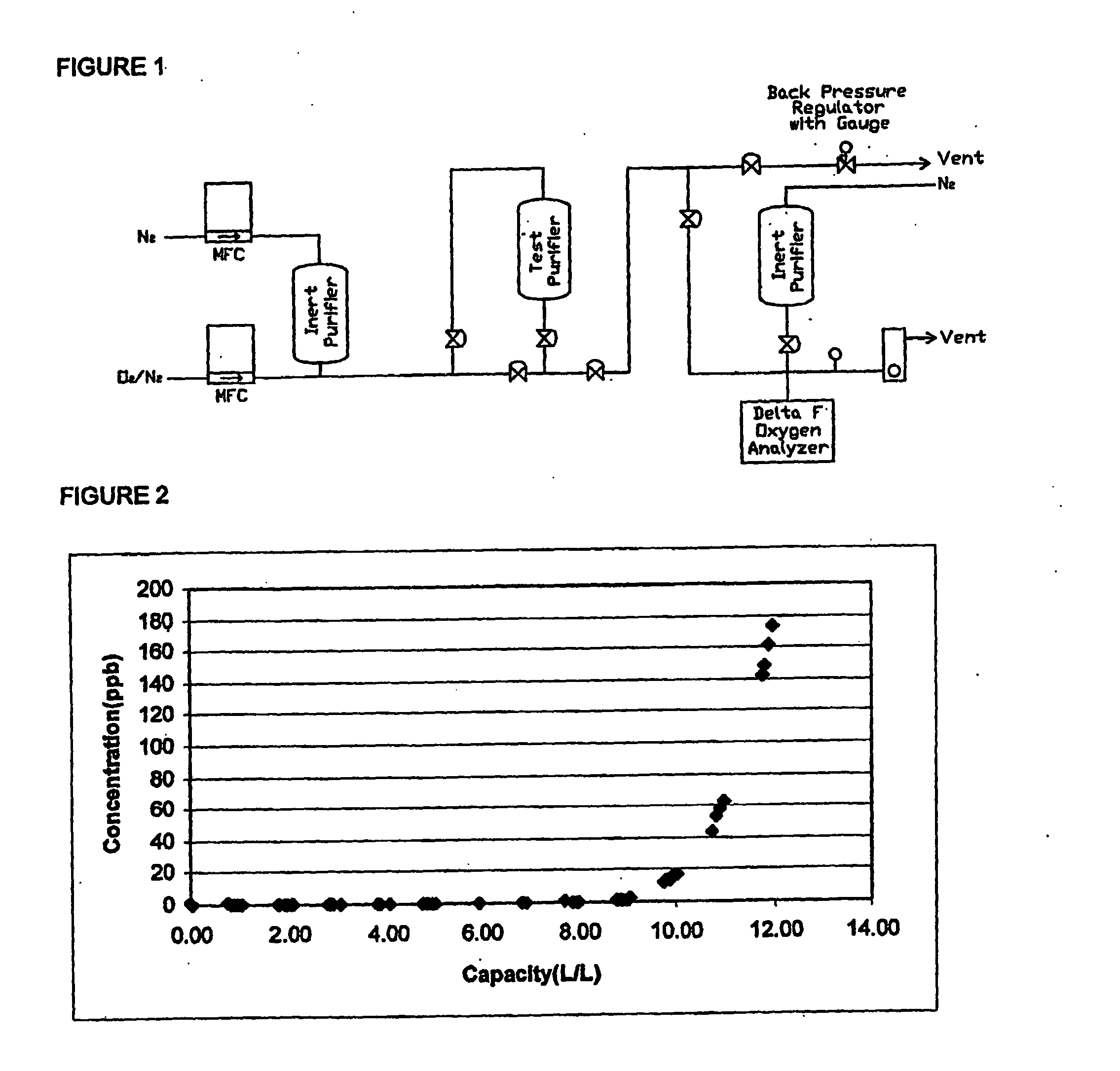
[0040]FIG. 1 represents the experimental setup. Mass flow controllers (MFCs) were used to maintain the flow rates of the 944 ppm O2 standard and the purified nitrogen (N2) to attain a challenge gas containing 15 ppm of O2. A backpressure regulator was used to vent and maintain the pressure during purging of the test manifold. A Nanotrace Oxygen Analyzer (Delta-F) was used to measure the O2 concentration. The lower detection limit o...


PUM

PropertyMeasurementUnit
temperatureaaaaaaaaaa

Abstract

The invention is a method for the decontamination of CO2 to a sufficient level of purity to allow it to be used in the semiconductor industry. The invention comprises the exposure of fluid CO2 to a combination metallic states of at least one metal under the appropriate conditions for removal of contaminants. The adsorbents are then decontaminated/activated to return the adsorbent to a mixed oxidation state and allow further rounds of decontamination. The adsorbents are selected to be complimentary to each other, preferentially adsorbing different contaminants. Additionally, the adsorbents are selected to undergo reduction differently such that upon regeneration only a portion of the metals are reduced and the adsorbent is returned essentially to its original state.

Description

CROSS-REFERENCES TO RELATED APPLICATIONS [0001] This application claims the benefit of priority of U.S. provisional application Ser. No. 60 / 419,390 filed Oct. 17, 2002 which is incorporated herein by reference in its entirety. This application is related to U.S. patent application Ser. No. ______ filed Oct. 17, 2002 entitled “METHOD OF RESTRICTED CARBON DIOXIDE PURIFICATION” which is incorporated herein by reference in its entirety.BACKGROUND OF THE INVENTION [0002] Carbon dioxide (CO2) is used in a wide variety of industrial processes and products from the carbonation of beverages to the generation of semiconductors. Industrial applications for CO2 include wafer cleaning, removal of residual photoresist, low K dielectric annealing and cleaning, use as laser gases, particle removal and plasma generation. The presence of contaminants in such ultrahigh purity applications can result in products that are unusable in the case of semiconductor applications or the damage of optics and las...

Claims


Application Information

Patent Timeline
Patent Type & Authority Applications(United States)
IPC IPC(8): C01B32/50B01D53/02B01D53/04B01J20/06B01J20/34C01B17/16
CPCB01D53/02B01J20/3458B01D2253/10B01D2253/112B01D2256/22B01D2257/104B01D2257/308B01D2257/404B01D2257/406B01D2257/702B01D2257/80B01D2259/40083B01D2259/402B01J20/06B01J20/3483B01J2220/42C01B31/20Y02C10/08B01J20/3433B01D53/04C01B32/50Y02C20/40B01D53/62
Inventor ALVAREZ JR, DANIELSPIEGELMAN, JEFFREY J.HOLMES, RUSSELL J.
Owner ENTEGRIS INC
Why Eureka
Try Eureka