

Applications of light-emitting nanoparticles
- Summary
- Abstract
- Description
- Claims
- Application Information
AI Technical Summary
Benefits of technology
Problems solved by technology
Method used
Image

Examples
example 1
Transmission Electron Microscopy
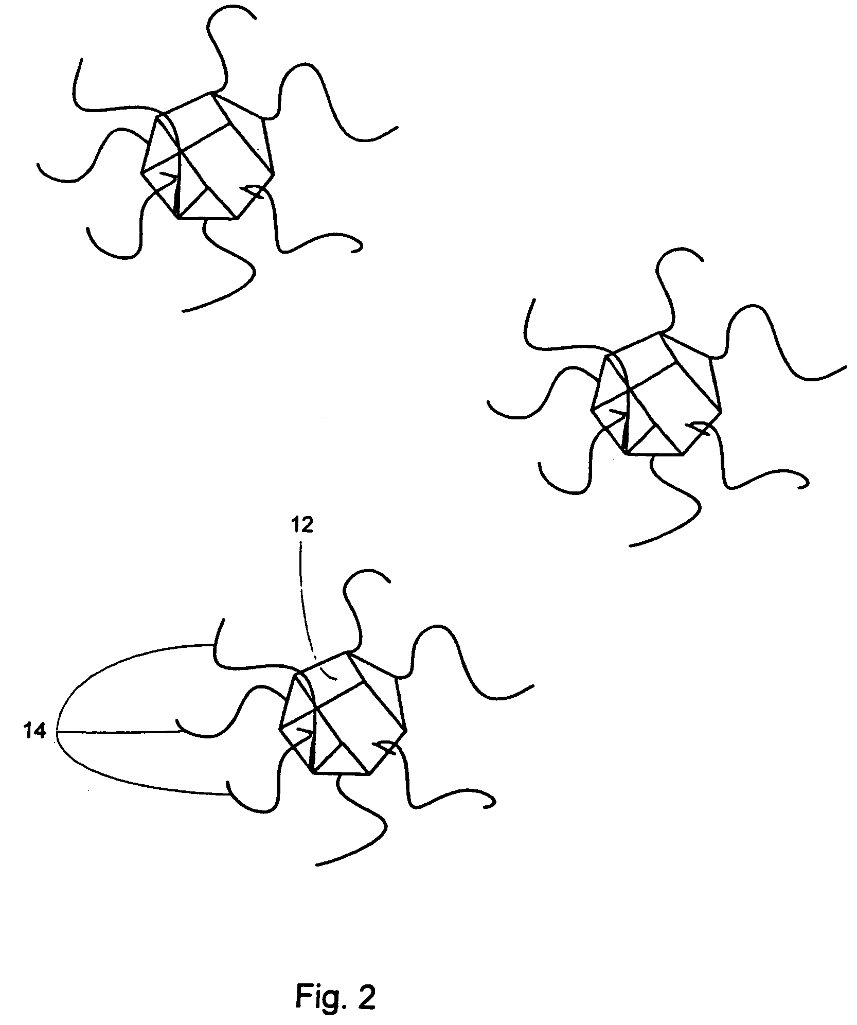
[0196] A TEM image of an organic-monolayer stabilized 40 Å diameter Si nanoparticle exhibits a crystalline core with a well-defined faceted surface. The lattice spacing was 3.1 Å, characteristic of the distance separating the (111) planes in diamond-like Si. Si nanoparticle may propagate through a radical mechanism as shown:
Equation 1=(Ph)2SiH2→(Ph)2SiH.
Equation 2=2(Ph)2SiH.→H(Ph)2Si—Si(Ph)2H
The benzene rings may help stabilize the diphenylsilane radical intermediates by delocalizing the electron charge. These free radicals can react to form Si—Si bonds. The octanol molecules subsequently displace the phenyl groups and cap the Si particle surface. There are other possible mechanisms that include the formation and degradation of other intermediate products, such as triphenyl and tetraphenyl silane. Furthermore, this reaction may not proceed through a free radical mechanism.
example 2
Extraction of Silicon Nanoparticles
[0197] Size-monodisperse 15 Å diameter Si nanoparticles were obtained by reacting diphenylsilane in pure octanol with subsequent redispersion in ethanol. A fraction of the sample is made up of larger Si nanoparticles that form during the reaction that do not resuspend in ethanol due to their hydrophobicity, whereas the extreme surface curvature of the 15 Å diameter nanoparticles provides ethanol with “access” to the polar Si—O—C capping layer termination to enable the size-selective dispersion of 15 Å diameter Si nanoparticles. The 15 Å diameter nanoparticles are barely perceptible in TEM images obtained with samples dispersed on a carbon-coated TEM grid. Low-resolution images of aggregates of these 15 Å diameter nanoparticles show that the samples contain little size variation. For comparison, TEM images of larger Si nanoparticles with diameters ranging from 25 to 35 Å produced by performing the synthesis in sc-hexane with increased Si:octanol mo...
example 3
In Situ Energy-Dispersive X-Ray Spectroscopy
[0199] In situ energy-dispersive X-ray spectroscopy (EDS) measurements of the nanoparticles imaged by TEM revealed Si in high abundance with the presence of oxygen and carbon as well. A quantitative analysis of the elemental ratios was not possible since the supporting substrate was carbon containing a measurable amount of residual oxygen.
[0200]FIG. 12 illustrates an example of energy-dispersive X-ray spectroscopy (EDS) analysis of an exemplary nanoparticle composition. The EDS data of the exemplary nanoparticle. The copper (Cu) peak results from the copper TEM grid used as a support. Other peaks shown are the carbon (C), oxygen (O) and silicon (Si) peak
PUM
| Property | Measurement | Unit |
|---|---|---|
| Fraction | aaaaa | aaaaa |
| Fraction | aaaaa | aaaaa |
| Fraction | aaaaa | aaaaa |
Abstract
Description
Claims
Application Information