High intensity and high power solid state laser amplifying system and method

a laser system and laser technology, applied in the direction of laser details, excitation process/apparatus, active medium shape and construction, etc., can solve the problems of limiting and even reducing achievable power and intensity gains, inefficient or even inoperable conventional laser and amplifying systems, and achieving high power and high intensity lasers. , to achieve the effect of efficient reflection, efficient heat dissipation, and high power

Inactive Publication Date: 2005-12-08
JMAR LLC A DELAWARE LLC
View PDF10 Cites 4 Cited by
  • Summary
  • Abstract
  • Description
  • Claims
  • Application Information

AI Technical Summary

Benefits of technology

[0028] The four-pass amplifier also may include two reflectors. The first reflector is in the beam path downstream from the NPR and returns the beam after the first and third passes to begin the second and the fourth passes. The second reflector is disposed in the deflection path of the second PBS to receive and return the beam between the second and third passes. The reflectors include optical mirrors that receive and return the input beam. Laser reflector materials in high power and high intensity applications can be fabricated from materials that operate to optically reflect and to transmit light, that can dissipate heat efficiently and/or that are structurally robust. Hard boundary reflectors such as metal-backed mirrors may be disadvantageous for certain applications since the amplified laser light may destroy the metal-backed mirrors.
[0029] In an exemplary embodiment, the present invention provides that one or both of the reflectors include a Porro prism. Porro prisms include 45°-90°-45° solid structures constructed of substantially clear materials. Porro prisms efficiently reflect the entering light energy without the need for reflective coatings. Furthermore, Porro prisms increase the uniformity of the laser beam by inverting the beam after the first and third passes through the amplifier. As a result, the beam passes through the four-pass amplifier twice in one orientation, and twice in an inverted orientation to homogenize (e.g., smooth, counteract or cancel out) imperfections in the amplification profile within the laser crystal rods.
[0030] In an exemplary embodiment, the present invention provides that the first and the second PBS's have polarizing coatings on an outside surface. In another exemplary embodiment, the present invention provides that the first and the second PBS's are solid PBS's having polarizing coatings on an interior surface. For example, the PBS might constitute a solid, cubed-shaped optically-transparent device that has a polarizing coating on an interior diagonal plane. The solid PBS's are especially applicable in the field of high-powered laser applications. High power and high intensity laser systems may produce beam intensities of, for example, a few gigawatts per square centimeter (GW/cm2), which when focused, may exceed, for example, 1015 W/cm2 at a particular focal plane. The positioning of the polarizing coating in a high-powered laser amplifier avoids the formation of hot spots at the air-coating boundary since...

Problems solved by technology

However, such high power and high intensity lasers are very hard to obtain with a high quality beam and a short pulse duration.
However, conventional laser amplifiers have design and performance aspects that limit and even reduce achievable power and intensity gains.
At high power and high intensity, heat generated by the laser pump light can create thermal optical effects and thermal stresses in laser and amplifying systems which distort the light beam, making conventional laser and amplifying systems inefficient or even inoperable.
Furthermore, the energy contained in high power and high intensity laser beams can permanently damage, if not instantly vaporize, components of conventional laser and amplifying systems.
Varying illumination intensities and thus varying indices of refraction also occur due to non-uniform energy densities resulting from laser pumping sources.
As a result, phase delays occur in the regions of higher intensity, distort the focus of the light beam and limit the gains in intensity and power.
A varying index of refraction also alters the optical path of affected portions of the beam, causing the whole beam or portions of the beam to collapse into focus points.
As a result of the B-integral effects and other sources of distortion to the light beam (such as optical imperfections in the laser path), high power and high int...

Method used


Image

  • High intensity and high power solid state laser amplifying system and method
  • High intensity and high power solid state laser amplifying system and method
  • High intensity and high power solid state laser amplifying system and method

Examples


Embodiment Construction

[0056] In accordance with the present invention, a system and a method are provided that produce high power and high intensity laser beams of high quality.

I. System and Method Overview

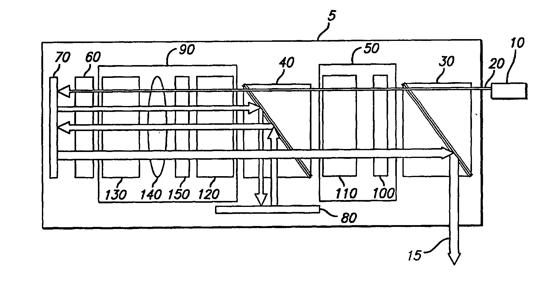
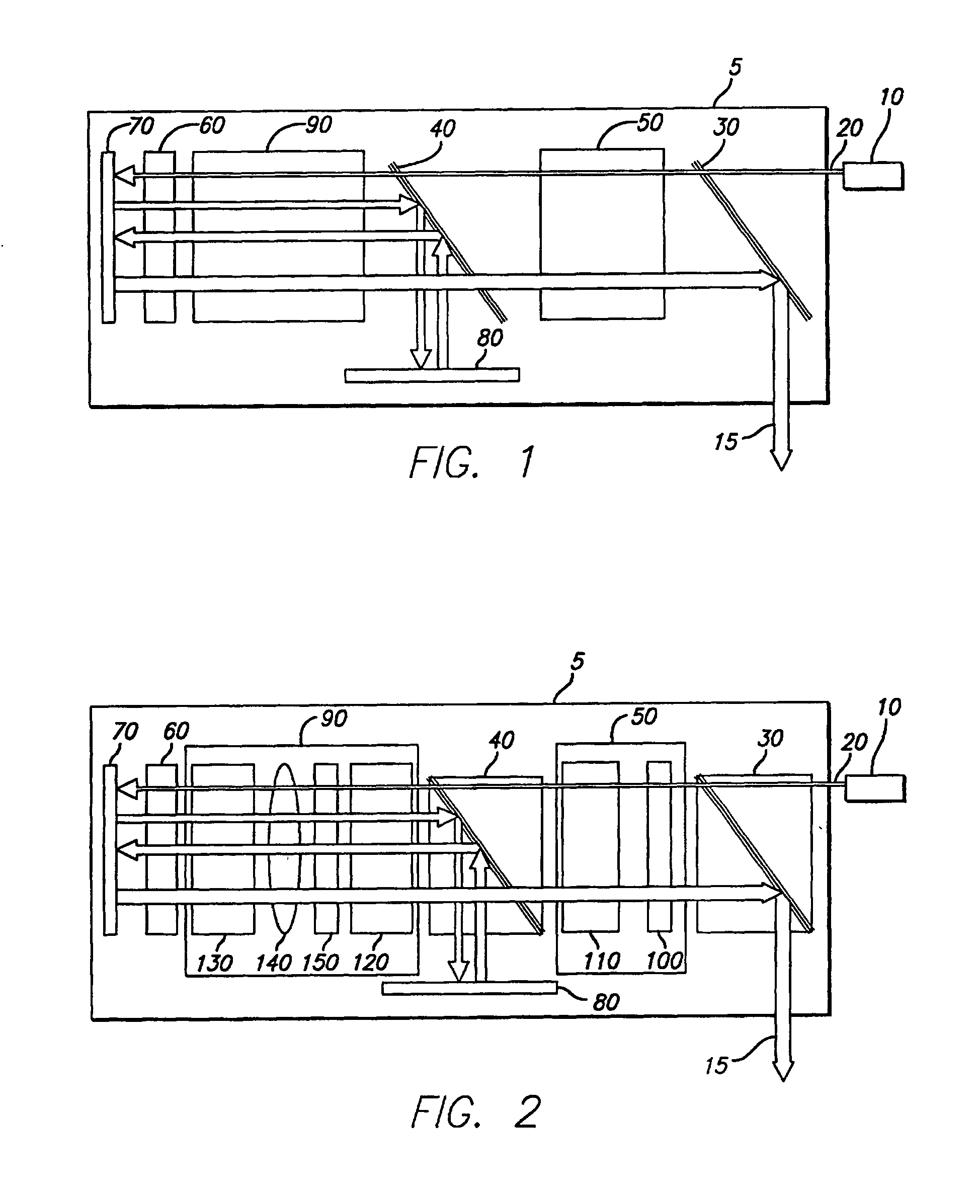
[0057] In an exemplary embodiment as illustrated in FIG. 1, the present invention provides an external laser source 10 (e.g., a master oscillator) and a laser amplifier 5. The external laser source 10 generates an input beam 20 that is amplified by the laser amplifier 5. The laser amplifier 5 includes a first polarizing beam splitter (PBS) 30, a second PBS 40, a directional polarization rotator (DPR) 50, a non-directional polarization rotator (NPR) 60, a first reflector 70, a second reflector 80 and a pumping module 90. In the illustrated embodiment, the laser amplifier 5 is configured as a four-pass optical amplifier. However, the present invention also contemplates an n-pass optical amplifier in which n is a cardinal number. Furthermore, the present invention contemplates modifications by those sk...


PUM


Abstract

Systems and methods are provided for achieving high power and high intensity laser amplification. In a four-pass optical amplifying system, a linear polarized optical beam is directed by various optical elements four times through an optical amplifier. The optical amplifier is transversely pumped by a pumping energy source that includes laser diode arrays. The pumping module and the other optical components are provided to counteract thermal lensing effects, induced thermal birefringence effects and to achieve enhanced amplification and efficiencies.

Description

[0001] This is a divisional patent application of co-pending U.S. patent application Ser. No. 09 / 907,154, filed Jul. 16, 2001, entitled “High Intensity and High Power Solid State Laser Amplifying System and Method”, which is a continuation-in-part of co-pending U.S. patent application Ser. No. 09 / 689,539, filed Oct. 12, 2000, entitled “Beam Correcting Laser Amplifier”, which itself is based on U.S. Provisional Patent Application Ser. No. 60 / 159,521, filed Oct. 15, 1999, entitled “Beam Correcting Laser Amplifier”. Priority is claimed to the above-identified co-pending U.S. Patent Application(s) and to the above-identified U.S. Provisional Patent Application. The disclosures of all of the above-mentioned applications are incorporated herein by reference in their entirety for all purposes.FIELD OF THE INVENTION [0002] The present invention generally relates to a system and a method for amplifying coherent light and, more specifically, to a system and a method for amplifying coherent li...

Claims


Application Information

Patent Timeline
IPC IPC(8): H01S3/094H01S3/06H01S3/063H01S3/08H01S3/09H01S3/091H01S3/0941H01S3/23
CPCH01S3/005H01S3/0064H01S3/0606H01S3/063H01S3/08072H01S3/094076H01S3/094084H01S3/0941H01S3/1103H01S3/1106H01S3/1611H01S3/1643H01S3/2316H01S3/2341
Inventor RIEGER, HARRYCAMBEAU, SERGE
Owner JMAR LLC A DELAWARE LLC
Why Eureka
Try Eureka