[0010] A new form of high efficiency, high power, low emissions engine based on the Otto cycle, but improving on it, designated “High Compression Conversion Exchange” cycle, or HCX cycle for short, is disclosed, which overcomes the fundamental problem of the Otto cycle. This application discloses in mathematical detail and physical preferred embodiments, simple and optimal ways to use the advantages and benefits of the new HCX cycle to achieve the highest
engine efficiency at light loads, and high power at full load, in an otherwise conventional IC engine, preferably in a homogeneous charge
spark ignition engine which provides the maximum power at
high load and lowest tailpipe emissions through 3-way catalyst action, and best efficiency at light loads through
lean burn, fast burn combustion.
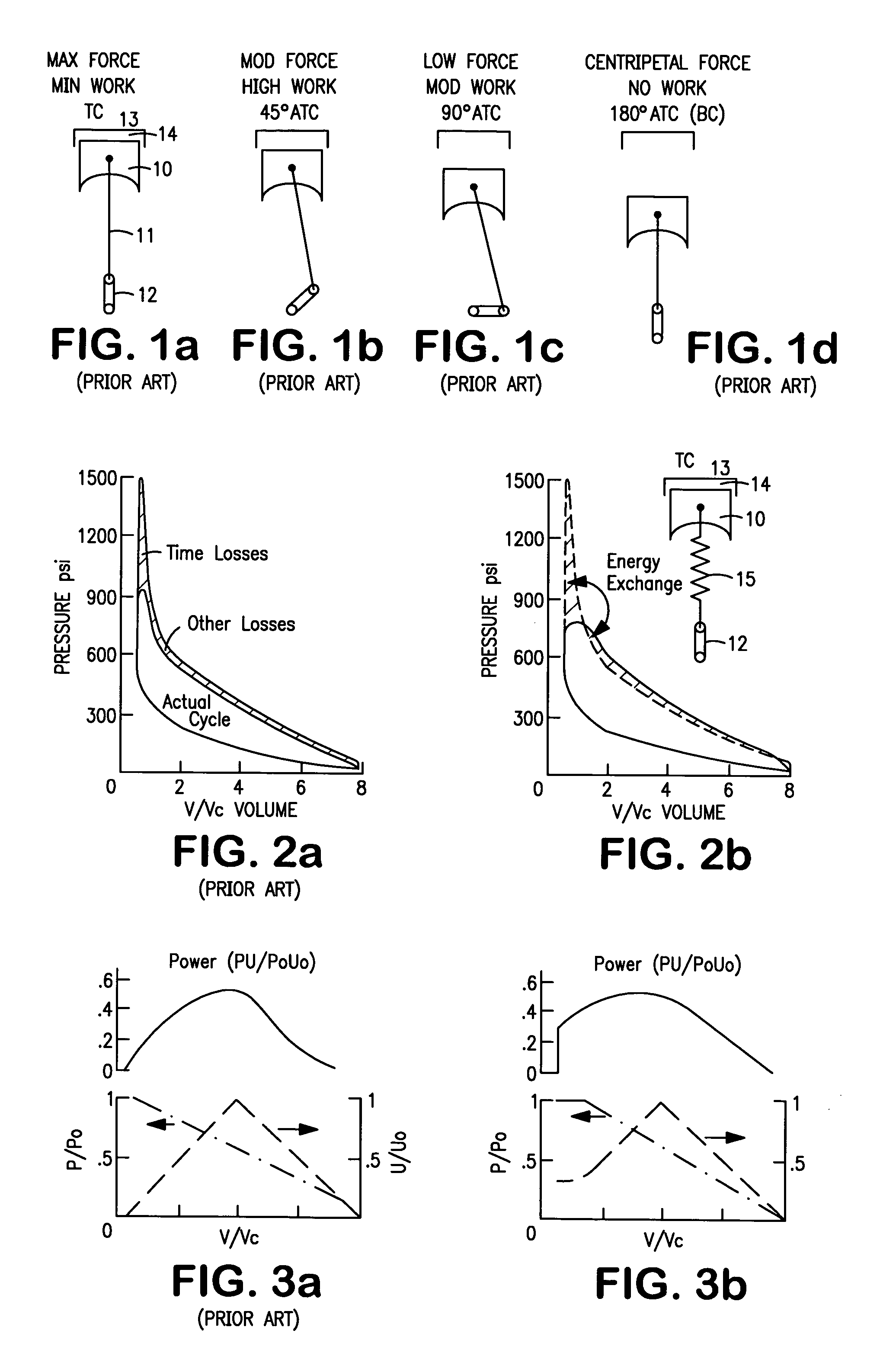
[0015] For the preferred embodiment where a steel spring is used to take up the excess force associated with the
pressure difference Pi−Pf, the
system operates by one or more spring means being further compressed from their pre-loaded compressed position (or elongated if under tension) around top center on the compression
stroke due to the gas pressures in the
combustion chamber exceeding the pre-
load force Fpre, the spring being compressed in relationship to the excess pressure which drops with spring compression due to the
gas expansion to attain an equilibrium position, storing the excess pressure as spring energy. The spring energy is then gradually released as the piston moves down and the pressure drops below Pf to the pre-load value Ppre, when the spring recovers to its pre-load position, having converted the potential excess pressure forces related to the high compression ratio occurring around TC, to a later point of
crank angle rotation where the potential excess forces can do work in rotating the engine
crank while having limited the peak pressures without the usual loss of
cycle efficiency which accompanies limited pressure cycles.
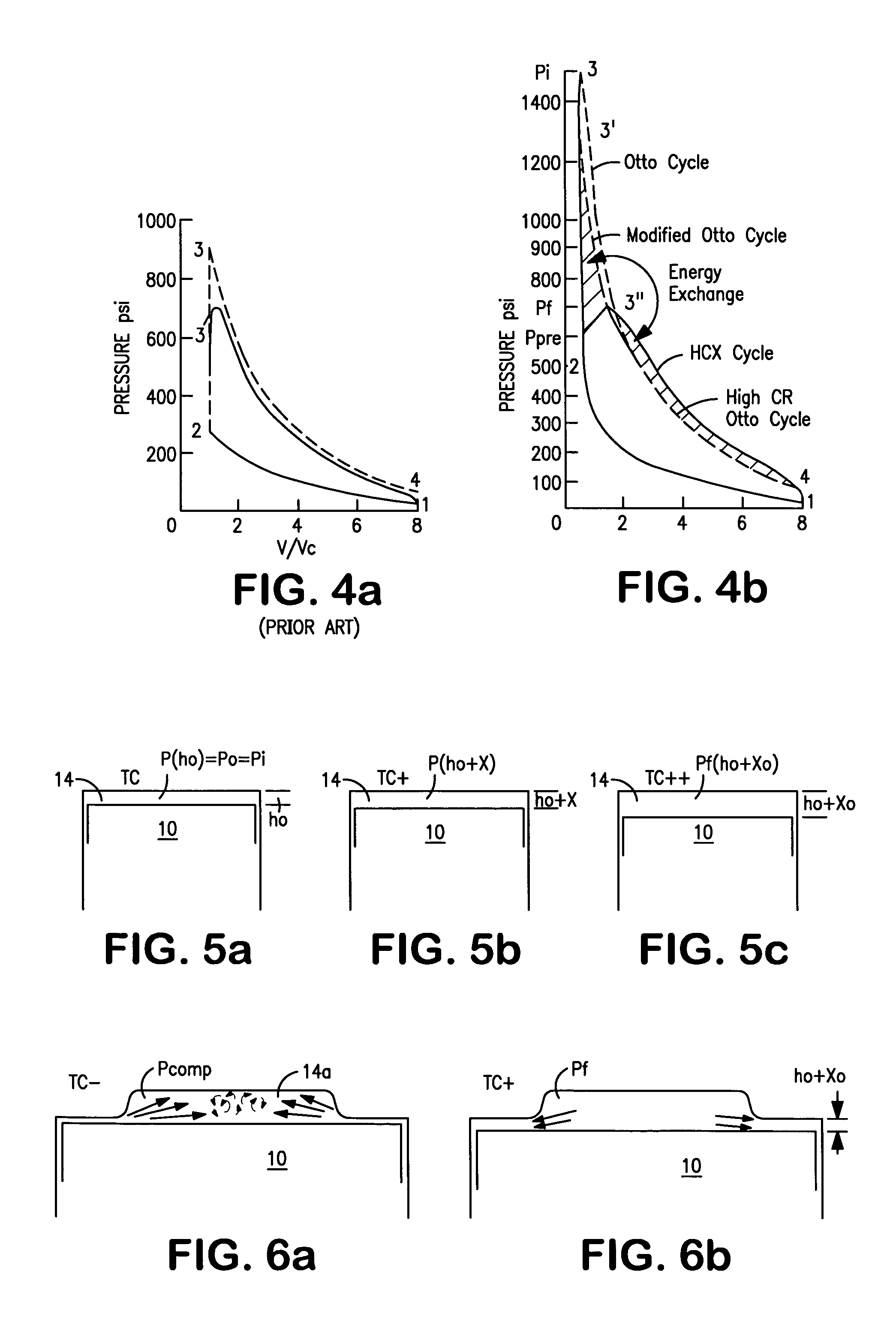
[0016] The HCX
system is further constructed and arranged such that the pressure Pcomp near the end of the compression stroke between 30° and 10° before TC, is approximately equal to the theoretical Otto cycle pressure, i.e. Pcom<Ppre, so that there is little, if any, drop in pressure due to the HCX
system at that point, so that, in terms of my patent and patent applications '107 and '058, the high air squish flow is not compromised.
[0017] In the typical automotive vehicle case, the engine is designed for 13:1 to 24:1 CR, defined as CR0, with effective CR (CReff) of 8:1 to 11:1 at WOT, or possibly higher for higher
octane fuels, but with CReff approximately equal to CR0 at typical driving
light load conditions, such as ⅓ of load for a given engine speed. This requires pre-loading of the flexible material in a precise way for a given spring constant k to meet this requirement. The flexible material is preferably spring material, especially of the steel type which has very low loss and can absorb, release, and return over 95% of the energy stored in it.
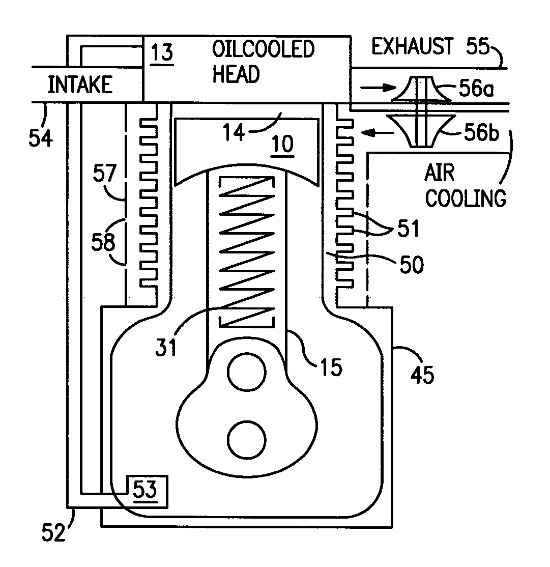
[0021] The advantages of the HCX cycle in terms of its higher efficiency and low
heat transfer under lean, fast-burn, light load conditions, leads to improved engine designs in any of a number of ways known to those versed in the art, such as using air-cooling instead of
water cooling (with higher cylinder wall temperatures) given the lower peak pressures and temperatures, for even lower heat transfer and higher
engine efficiency, while providing a simpler and lower cost
engine power-
plant with less
vulnerability to failures. A preferred embodiment of the HCX cycle engine is with the squish-flow, 2-valve, dual ignition engine disclosed in my patent '107 and
patent application '058, wherein the engine is designed on the basis of a high compression ratio of approximately 18 to 1 (CR0=18:1), where CRset is approximately 10:1, which improves the engine efficiency under all operating conditions, and particularly under ultra-lean, fast-burn conditions at light load, by providing high compression ratio and high squish flow at the
spark plug sites for even leaner and faster burn operation.
[0023] The HCX system allows for an improvement in
ignition timing, in that the
ignition timing can be set earlier, all other things being equal, since any excess in pressure prior to TC is stored in the spring and recoverable. In this way, a faster burn will occur with
peak pressure closer to TC, with the
excess energy associated with the
pressure difference Pi−Pf stored just after top center.

