
Apparatus and methods for control of waste treatment processes

a waste treatment process and apparatus technology, applied in the field of biological treatment, can solve the problems of exacerbated problems, insufficient capacity of the aeration unit 118 to provide sufficient oxygen, and inability to easily tailor a given biological population to the varying needs of the influent waste stream, so as to reduce the overall disposal volume and cost, and the effect of minimizing solid growth

Inactive Publication Date: 2006-01-05
ADVANCED TREATMENT SCI
View PDF24 Cites 23 Cited by
  • Summary
  • Abstract
  • Description
  • Claims
  • Application Information

AI Technical Summary

Benefits of technology

[0015] The preceding problems are addressed by the generation and introduction of specific biology populations with modified characteristics in stored substances, such as macro nutrients and carbon-based compounds, and which are customized to optimize waste treatment process by performing specific tasks during the main treatment processes while maintaining minimal solids growth. These bacteria may be grown from specialized mixes of activated sludge and waste influent by exposing these materials to controlled growing environments, e.g., in an isolated off-line treatment area. The controlled growing environment may be used to form phosphorous precipitants from waste effluents, thereby reducing the overall disposal volumes and costs associated with chemical additives.
[0018] In various embodiments, biologically available carbon is generated through extracellular solubilization and cell destruction, thereby enhancing the phosphorus-uptaking capacity of at least a portion of the second biological population.
[0020] Precipitation and solubilization of phosphate into solution can be enhanced by the mechanical addition of carbon dioxide, and the carbon dioxide can be introduced through the respiration of biomass. In some embodiments, the biomass includes the second biological population. In various embodiments, there is no flow between the off-line treatment vessel and the first treatment vessel during the controlling step.
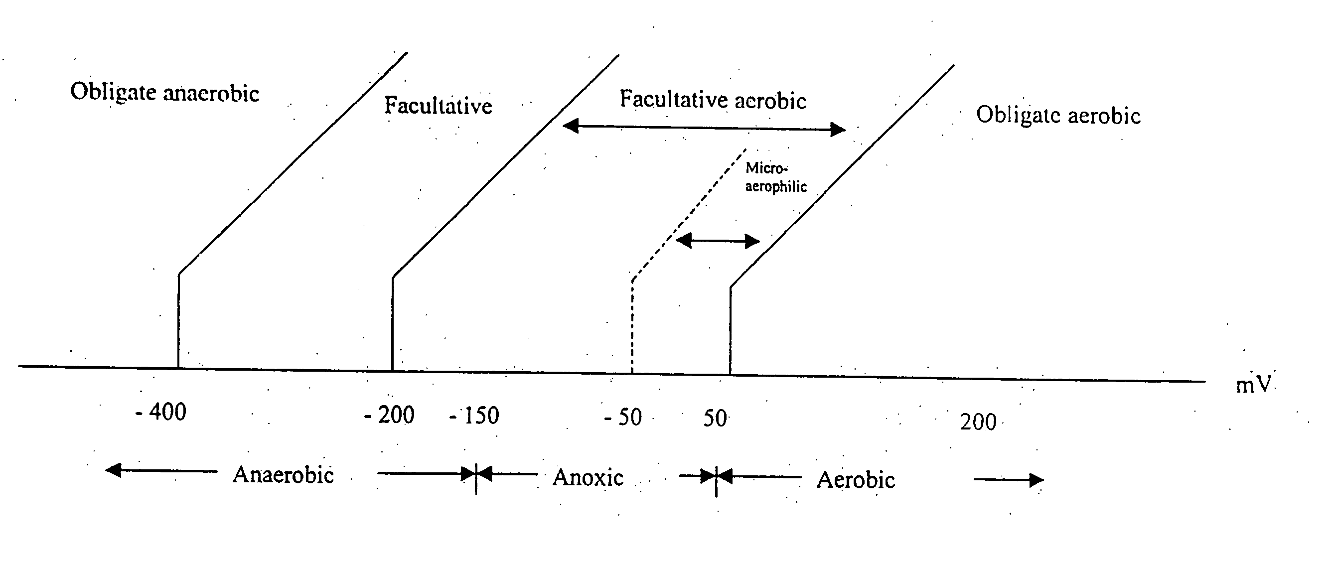
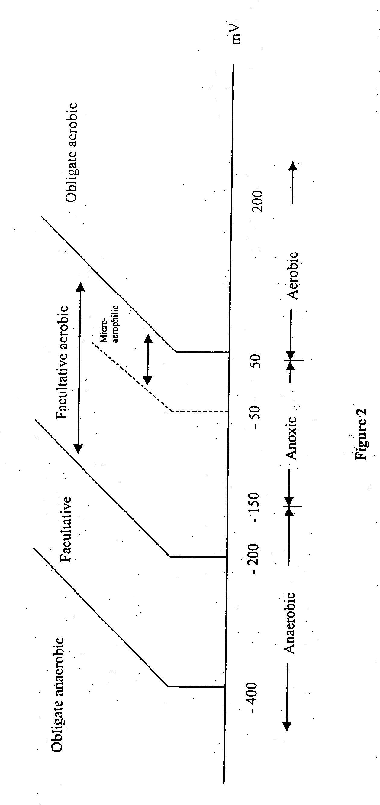
[0022] In other embodiments, the controlling step includes altering an ORP level in the drawn-off portion in a predetermined cyclical pattern, i.e. repeatedly increasing and decreasing the ORP level, to facilitate carbon utilization by the PAO, which enhances the second biological population's ability for biological uptake of phosphorus in the first treatment vessel upon return of a fraction of the drawn-off portion to the first treatment vessel. Specifically, repeated cycling of the ORP level in the drawn-off portion allows PAO population to utilize carbon, which is typically unavailable in the main treatment process, to further release and uptake phosphorus released to the liquid component of the waste stream upon contact with the first biological population. This, in turn, enhances second biological population's ability to uptake and hold increased amount of phosphorus when a fraction of the drawn-off portion is returned to the first treatment vessel.

Problems solved by technology

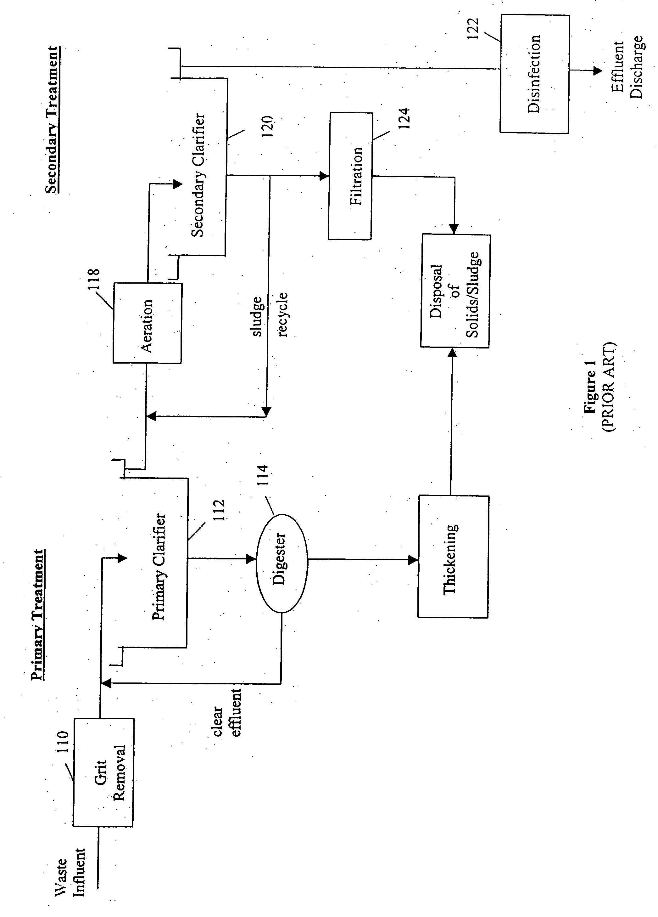
In some processes the aeration unit 118 has insufficient capacity to provide sufficient oxygen to meet the biological metabolism requirements of the microorganisms present in the waste stream.
Recycling of these microorganisms is convenient and inexpensive, but unfortunately does not readily lend itself to the customized matching or tailoring of a given biological population to the varying needs of the influent waste stream.
These problems are exacerbated by the limited amount of flexibility most treatment plants have in manipulating the factors that favor a desired biological population profile.
Common to all of these processes, however, is generation of a waste stream of excess biology, generated because new growth exceeds death and decay.

Method used


Image

  • Apparatus and methods for control of waste treatment processes
  • Apparatus and methods for control of waste treatment processes
  • Apparatus and methods for control of waste treatment processes

Examples


example 1

[0060] The following procedure selects for facultative anaerobes, independent of nitrifiers, at the expense of obligate aerobes, to specifically augment biology that rapidly breaks down particulate cBOD into soluble cBOD for utilization.

[0061] 1. Fill tank 130 with a combination of excess activated sludge and raw influent, providing a nominal suspended solids concentration of between 3,000 and 5,000 mg / liter.

[0062] 2. Mix contents of tank 130 using mixer 136 without aeration until the ORP is anaerobic, but not so low as to evoke sulfide generation by sulfate reducing bacteria, should there be sulfate present in the raw influent or waste sludge. The mixture can also settle (without mixing) to accelerate the drop in ORP. This mixing and settling should last for about 4 to 8 hours.

[0063] 3. Stop the mixing and allow the mixture to settle, providing a decantable volume of at least 25% of the volume of tank 130. This will require about 2 to 4 hours.

[0064] 4. Remove the high cBOD, hig...

example 2

[0068] The following procedure selects for facultative anaerobes and aerobes, preserving nitrifiers, at the expense of obligate aerobes, to specifically augment biology low in yield. This is particularly useful for the minimization of residual solids.

[0069] 1. Fill tank 130 with a combination of excess activated sludge and raw influent, providing a nominal suspended solids concentration of between 5,000 and 7,500 mg / liter.

[0070] 2. Mix contents of tank 130 using mixer 136 without aeration until the ORP is anaerobic, but not so low as to evoke sulfide generation by sulfate reducing bacteria, should there be sulfate in the raw influent or waste sludge. This mixing should last for between 8 hours and 3 days.

[0071] 3. Continue mixing with mixer 136, and aerate tank 130“aggressively” until the ORP is >100 mV for 24 hours, >150 mV for 12 hours, or >200 mV for 4 hours.

[0072] 4. Stop the aeration but continue mixing until the ORP is anaerobic for at least 48 hours. If the ORP does not c...

example 3

[0080] The following procedure selects for facultative aerobes and nitrifiers to reduce high yield organisms, and improves the nitrification / denitrification capacity. If available, a recycle stream high in ammonia and cBOD content can be used in place of, or in combination with the raw influent, as long as the cBOD (mg / liter) to NH3-N (mg / liter) ratio is greater than 3. Note that this ratio is referenced to ammonia nitrogen, not Total Kjeldahl Nitrogen (TKN).

[0081] 1. Fill tank 130 to approximately 75% full with activated sludge at a suspended solids concentration of between 2,500 and 7,500 mg / liter.

[0082] 2. Mix contents of tank 130 using mixer 136 and with aeration and / or settle until the ORP is aerobic and the ammonia content is <0.1 mg / liter.

[0083] 3. Stop the aeration.

[0084] 4. With continued mixing, fill about another 5 to 10% of the volume of tank 130 with additional raw influent. Monitor the ORP and nitrate concentrations until the nitrate concentrations are <0.1 mg / lite...


PUM

PropertyMeasurementUnit
concentrationaaaaaaaaaa

Abstract

Waste-treatment processes are enhanced through generation and introduction of specific biological populations customized to perform or favor specific tasks either during the main process, for the formation or precipitation of certain biological nutrients, or to accomplish solids formation reduction in a post-treatment process. These bacteria may be grown from specialized mixes of activated sludge and waste influent by exposing these materials to controlled environments (e.g., in an off-line treatment area). They may then be returned to the main process to perform certain tasks such as converting particulate cBOD into soluble cBOD for utilization, to reduce high solids yield organisms by supplementing the population characteristics with low yield organism characteristics, to provide biological nutrients or oxygenation assistance, to improve nitrification / denitrification efficiency, or to disfavor filamentous biology such as Norcardia sp.

Description

RELATED APPLICATIONS [0001] This application is a continuation-in-part of U.S. Ser. No. 10 / 985,265, filed on Nov. 10, 2004, which is a continuation of U.S. Ser. No. 10 / 658,575, filed on Sep. 9, 2003 (now U.S. Pat. No. 6,833,074), which is a continuation of U.S. Ser. No. 09 / 798,313, filed on Mar. 2, 2001 (now U.S. Pat. No. 6,660,163). The entire disclosures of these applications are incorporated herein by reference.BACKGROUND OF THE INVENTION [0002] 1. Field of the Invention [0003] The present invention relates to biological treatment of contaminated liquids and effluent, and, more particularly, to methods and apparatus for the creation and / or application of customized biology populations to biological processes, such as wastewater treatment. [0004] 2. Description of the Related Art [0005] Before being discharged to the environment, contaminated waters from municipal, commercial, and industrial sources frequently must be treated to prevent harmful impacts. The treatment processes use...

Claims


Application Information

Patent Timeline
Patent Type & Authority Applications(United States)
IPC IPC(8): C02F3/30
CPCC02F3/006C02F3/12C02F3/286C02F2209/04C02F3/34C02F3/348C02F3/30Y02W10/10Y10S210/906
Inventor MIKLOS, DANIEL ROBERT
Owner ADVANCED TREATMENT SCI
Learn More