Top anti-reflective coating polymer, its preparation method and top anti-reflective coating composition comprising the same

a technology of anti-reflective coating and polymer, which is applied in the direction of photosensitive materials, instruments, photomechanical equipment, etc., can solve the problems of reduced storage stability, difficult to produce on a commercial scale, and high production cost of hard pellicles

Inactive Publication Date: 2006-01-12
SK HYNIX INC
View PDF14 Cites 9 Cited by
  • Summary
  • Abstract
  • Description
  • Claims
  • Application Information

AI Technical Summary

Benefits of technology

[0019] In view of the above problems, a top anti-reflective coating polymer is disclosed which can be used in immersion lithography due to its water insolubility, which can prevent the multiple interference of lig

Problems solved by technology

Technical solutions for the use of F2 are satisfactory to some extent, but there are the following problems: 1) the mass production of high-quality CaF2 within a short time is limited, 2) since soft pellicles are likely to be deformed upon exposure to light at 157 nm, the storage stability is decreased, and 3) hard pellicles incur considerable production cost, and are difficult to produce on a commercial scale due to their nature of light refraction.
On the other hand, since suitable light sources, exposure equipment and masks are required to use an EUV laser, it is not yet suitable for practical use.
A problem encountered with the fabrication of a sub-50 nm semiconductor device is that an alteration in the critical dimension (CD) of a photoresist pattern inevitably takes place, during the process for the formation of an ultrafine pattern, b

Method used


Image

  • Top anti-reflective coating polymer, its preparation method and top anti-reflective coating composition comprising the same
  • Top anti-reflective coating polymer, its preparation method and top anti-reflective coating composition comprising the same
  • Top anti-reflective coating polymer, its preparation method and top anti-reflective coating composition comprising the same

Examples


example 1

Preparation of Top Anti-Reflective Coating Polymer

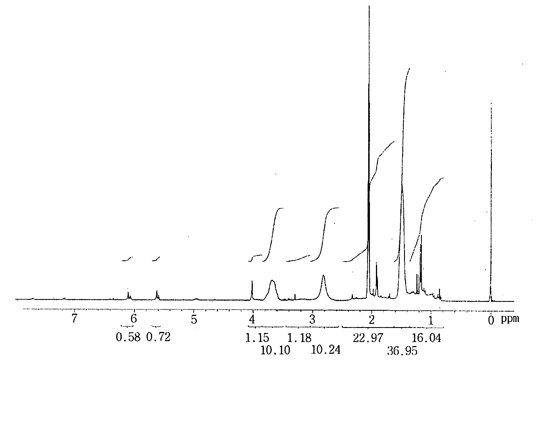
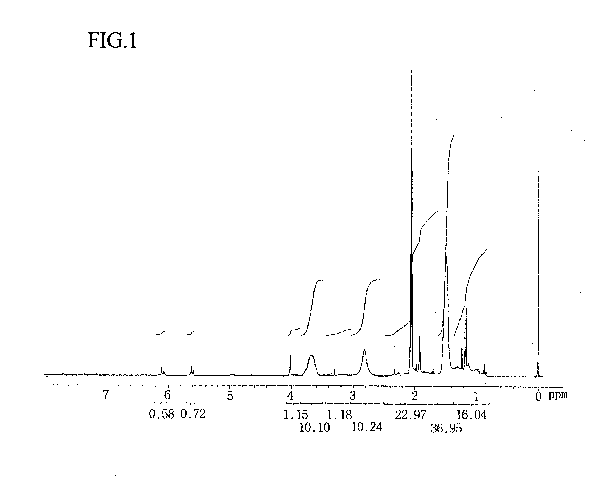
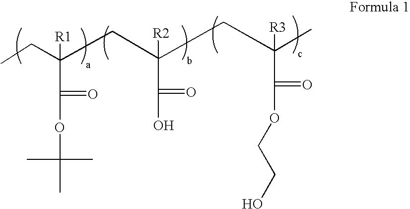
[0045] 12 g of t-butylacrylate, 5 g of acrylic acid, 3 g of 2-hydroxyethylmethacrylate and 0.4 g of AIBN were added to 200 g of PGMEA, and were then polymerized at 60° C. for 8 hours. After completion of the polymerization, the mixture was precipitated in ether, filtered, and dried in vacuo to yield 16 g of t-butylacrylate-acrylic acid-2-hydroxyethylmethacrylate copolymer, as a white solid, represented by Formula 2 below:

[0046] wherein a, b and c represent the mole fraction of each monomer, and are in the range between 0.05 and 0.9.

[0047] The structure of the copolymer was identified through 1H-NMR spectrum (FIG. 1).

example 2

Preparation of Top Anti-Reflective Coating Composition

[0048] 2.5 g of the polymer prepared in Example 1, and 0.04 g of L-proline, which is an amino acid, were dissolved in 100 g of n-butanol to give a top anti-reflective coating composition for use in immersion lithography.

example 3

Formation of Anti-Reflective Coating

[0049] The top anti-reflective coating composition prepared in Example 2 was coated on a wafer at 2,000 rpm to form an anti-reflective coating. The thickness, light transmission (at 193 nm), and reflective index of the anti-reflective coating were shown to have 47 nm, 93%, and 1.60, respectively.


PUM

PropertyMeasurementUnit
Temperatureaaaaaaaaaa

Abstract

Disclosed herein are top anti-reflective coating polymers used in a photolithography process, methods for preparing the anti-reflective coating polymer, and anti-reflective coating compositions comprising the disclosed anti-reflective coating polymers. The top anti-reflective coating polymers are used in immersion lithography for the fabrication of a sub-50 nm semiconductor device. The top anti-reflective coating polymer is represented by Formula 1 below:
wherein R1, R2 and R3 are independently hydrogen or a methyl group; and a, b and c represent the mole fraction of each monomer, and are independently in the range between about 0.05 and about 0.9. Because the disclosed top anti-reflective coatings are not soluble in water, they can be used in immersion lithography using water as a medium for the light source. In addition, since the top anti-reflective coatings can reduce the reflectance from an underlayer, the uniformity of CD is improved, thus enabling the formation of ultrafine patterns.

Description

BACKGROUND [0001] 1. Technical Field [0002] Anti-reflective coating polymers used in a photolithography process, which is one of the fabrication processes for a semiconductor device are disclosed. A method for preparing the anti-reflective coating polymer, and an anti-reflective coating composition comprising the anti-reflective coating polymer are also disclosed. The disclosed anti-reflective coating polymers can be used in immersion lithography for the fabrication of sub-50 nm semiconductor devices. [0003] 2. Description of the Related Art [0004] A photolithography process is a process for the transfer of a semiconductor circuit pattern formed on a photomask to a wafer. Photolithography is one of the most important steps in determining the fineness or side and integration density of circuits in the fabrication of semiconductor devices. [0005] In recent years, as the integration density of semiconductor devices has increased, new techniques have been developed that are adapted to f...

Claims


Application Information

Patent Timeline
IPC IPC(8): G03C1/492
CPCG03F7/091C08F220/18C08F220/1804C09D133/06C08F220/06C08F220/281G03F7/168G03F7/322
Inventor JUNG, JAE-CHANG
Owner SK HYNIX INC
Why Eureka
Try Eureka