
Lithographic mask and manufacturing method thereof

a technology of lithographic mask and manufacturing method, applied in the field of lithographic mask, to achieve the effect of suppressing the amount of sulfuric acid components, and promoting the forming reaction of foreign matter

Active Publication Date: 2006-01-26
HOYA CORP
View PDF3 Cites 19 Cited by
  • Summary
  • Abstract
  • Description
  • Claims
  • Application Information

AI Technical Summary

Benefits of technology

The invention provides a method of manufacturing a lithographic mask that can control the deposition of ammonium sulfate and prevent the formation of foreign matter when exposed to high power exposing means. The method includes steps of forming a pattern on a substrate, cleaning the substrate, and removing a surface layer portion of the pattern that contains sulfate ions. The invention also provides a lithographic mask that can prevent the formation of ammonium ions and suppress the generation of ammonia when exposed to high power exposing means. The method and mask can be used in the manufacturing of semiconductor devices, such as integrated circuits, using high power exposing devices.

Problems solved by technology

For this reason, there is a problem in that the formation of some deposit is promoted by a laser irradiation and the deposit becomes a foreign matter to stick onto the photomask.
However, it has been found that a sulfuric acid component derived from the sulfuric acid type detergent used at the cleaning step described above is adsorbed into a photomask surface and is removed with difficulty, and therefore, the sulfuric acid component remains in the photomask after the cleaning.
Therefore, there is a problem in that the formation of a deposit can be promoted more easily and a foreign matter is generated more remarkably, resulting in a great influence on quality.

Method used


Image

  • Lithographic mask and manufacturing method thereof
  • Lithographic mask and manufacturing method thereof
  • Lithographic mask and manufacturing method thereof

Examples


example 1

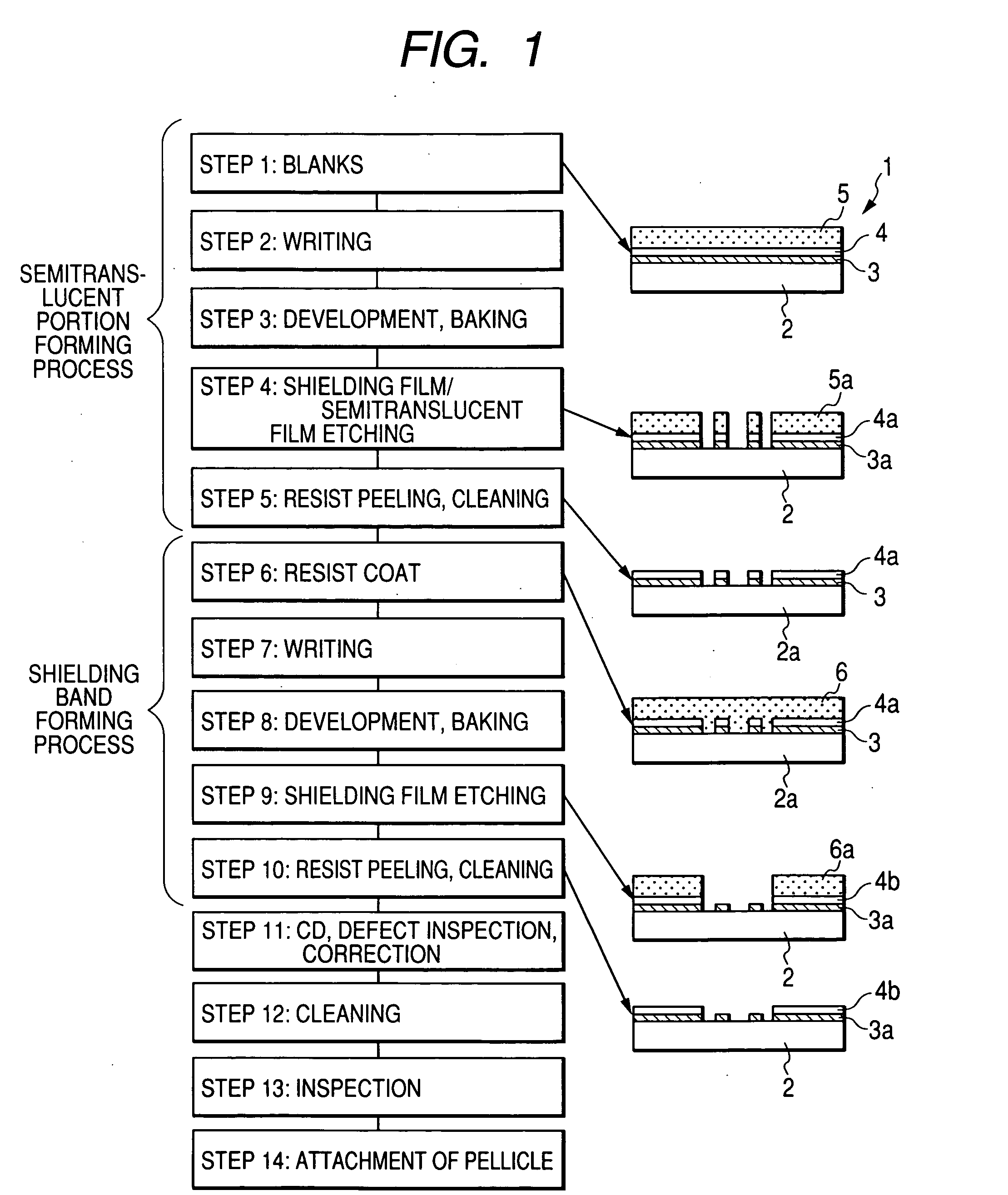
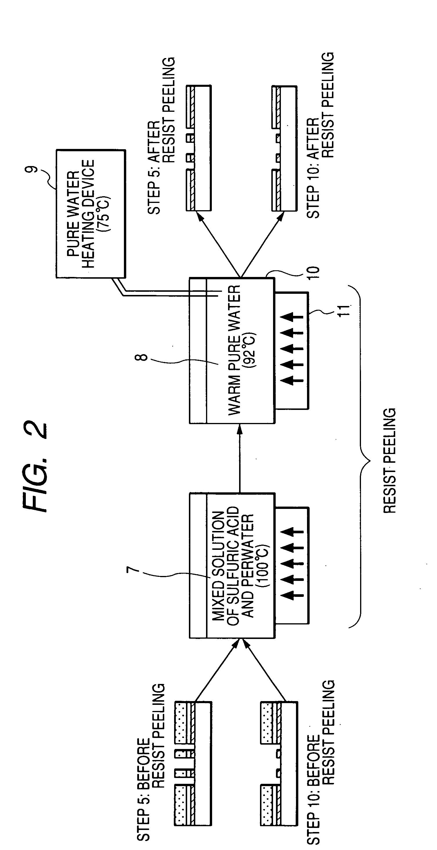
[0093]FIG. 1. shows an example of the flow of a method of manufacturing a halftone type phase shift mask to be a kind of a photomask.

[0094] First of all, there is prepared a photomask blank 1 in which a semitranslucent film 3 having a single layer structure constituted substantially by a metal such as molybdenum, silicon and nitrogen is formed on a transparent substrate 2, a chromium type shielding film 4 is formed thereon, and furthermore, a resist film 5 is formed thereon (FIG. 1 (step 1)). The semitranslucent film 3 is formed on the transparent substrate 2 by reactive sputtering (DC sputtering) in a mixed gas atmosphere of argon (Ar) and nitrogen (N2) (Ar:N2=10% :90%, pressure: 0.2 Pa) using a mixing target (Mo:Si=8:92 mol %) of molybdenum (Mo) and silicon (Si). The photomask blank 1 is used for an ArF excimer laser (a wavelength of 193 nm) having a transmittance of 5.5% and a phase shift amount of approximately 180 degrees.

[0095] Next, the resist film 5 is subjected to writing...

example 2

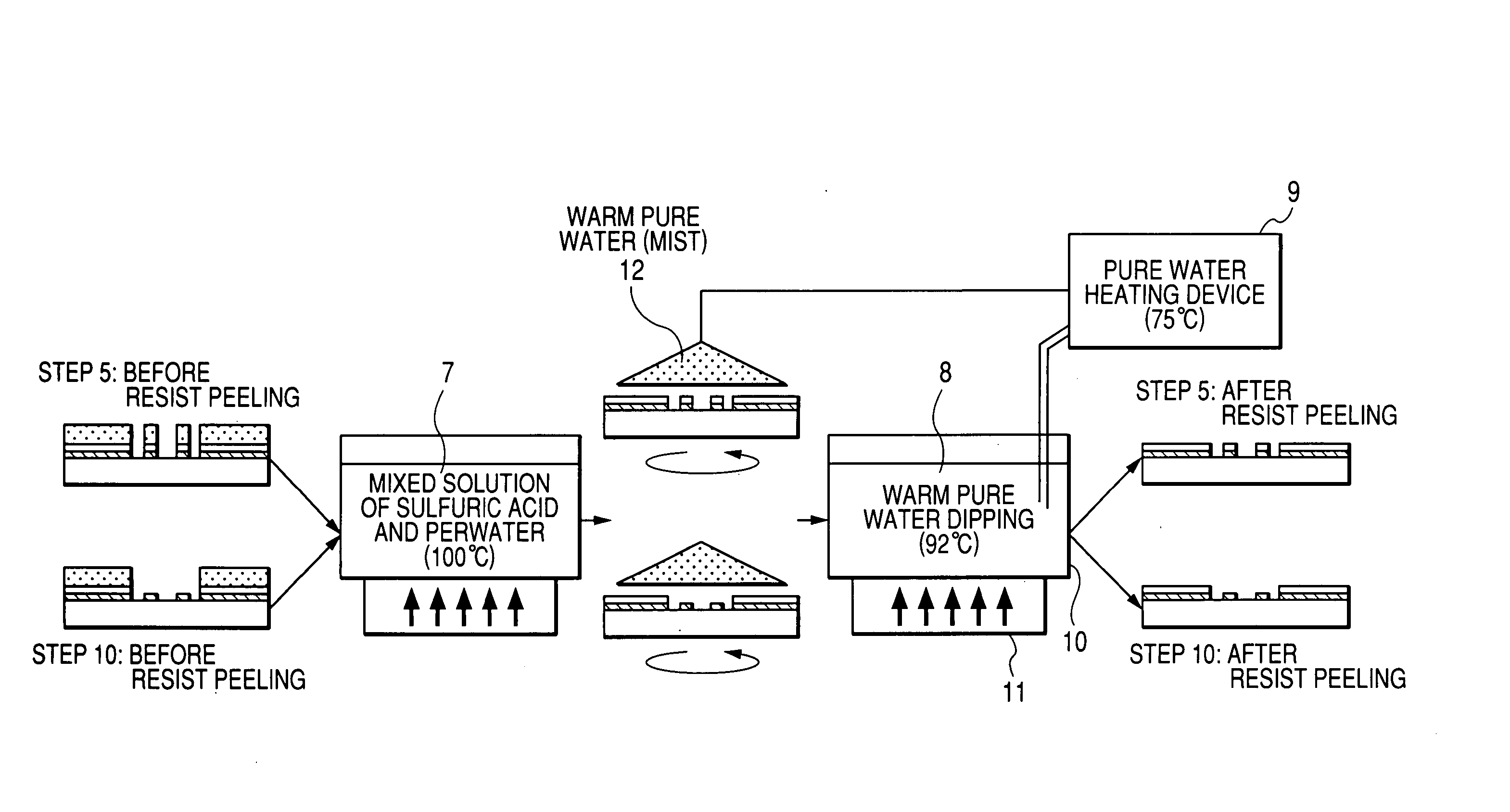
[0103] An example 2 is another example of the execution of the sulfuric acid removing step and FIG. 3 is a view for explaining the sulfuric acid removing step according to the example 2.

[0104] In the example, at the rinse step using warm pure water at 92° C. in the example 1, a spin treatment is executed while discharging a warm pure water mist 12 at 75° C. and a dipping treatment at 92° C. is used as a next rinse step.

[0105] According to the example, the supply of the warm pure water of the pure water heating device 9 is limited by only the same dipping treatment as that in the example 1. For this reason, a liquid substitution efficiency in the warm pure water dipping vessel 10 is deteriorated and the sulfuric acid removing step (a time required for the treatment of the warm pure water) is prolonged. According to circumstances, a warm water resistance is not sufficient. Consequently, the optical characteristic of a semitranslucent film is changed. By setting a spinning method hav...

example 3

[0108] An example 3 is a further example of the execution of the sulfuric acid removing step and FIG. 3 is a view for explaining the example 1. In the example, a mixed solution of sulfuric acid and perwater at 100° C. was used in resist stripping at the steps 5 and 10 and a normal low temperature rinse (a room temperature to 40° C.) was carried out, and warm pure water at 92° C. was used in cleaning before the attachment of a pellicle at the step 12.

[0109] As a result, the concentration of the sulfate ion after the cleaning was equal to that in the example 1.

[0110] According to the example, therefore, it is possible to reduce the deposition of an ammonium sulfate type foreign matter in the same manner as in the example 1.


PUM

PropertyMeasurementUnit
temperatureaaaaaaaaaa
wavelengthaaaaaaaaaa
temperatureaaaaaaaaaa

Abstract

Cleaning is carried out by using a sulfuric acid type detergent at a resist stripping and cleaning step (step 5) in a semitranslucent portion forming process and a resist stripping and cleaning step (step 10) in a shielding band forming process, and a sulfuric acid removing step of partially or wholly removing a surface layer portion in a pattern into which a sulfate ion is adsorbed is then carried out to effectively remove the adsorbed sulfate ion.

Description

[0001] This application claims foreign priority based on Japanese Patent application No. 2004-188157, filed Jun. 25, 2004, the contents of which is incorporated herein by reference in its entirety. BACKGROUND OF THE INVENTION [0002] 1. Field of the Invention [0003] The present invention relates to a method of manufacturing a lithographic mask such as a photomask to be used for manufacturing a semiconductor device and the lithographic mask, and to a method of manufacturing a lithographic mask to be used in an exposing device utilizing such high power exposing means as to promote the forming reaction of an ammonium sulfate type foreign matter, for example, an exposed light constituted by a laser beam having a wavelength of 200 nm or less such as an ArF excimer laser beam, and the lithographic mask. [0004] 2. Description of the Related Art [0005] In the formation of a transfer pattern in the manufacture of a semiconductor device, for example, an exposed light is irradiated on a resist ...

Claims


Application Information

Patent Timeline
Patent Type & Authority Applications(United States)
IPC IPC(8): G03C5/00C03C25/68G03F1/00G03F1/32G03F1/68G03F1/82G03F7/20G03F7/42H01L21/027H01L21/304
CPCG03F1/82G03F1/32G03F1/26
Inventor MORI, JUNJITAKUSHIMA, KATSUHIRO
Owner HOYA CORP
Learn More