Preparation of asymmetric membranes using hot-filament chemical vapor deposition

a technology of chemical vapor deposition and asymmetric membrane, which is applied in the direction of membranes, separation processes, coatings, etc., can solve the problems of undesirable reduction of one of these characteristics, liquids being filtered in this fashion experience pressure drop across the membrane filter, outgassing of liquid, etc., and achieve the effect of reducing pressure drop and less energy

Inactive Publication Date: 2006-02-23
MASSACHUSETTS INST OF TECH
View PDF9 Cites 15 Cited by
  • Summary
  • Abstract
  • Description
  • Claims
  • Application Information

AI Technical Summary

Benefits of technology

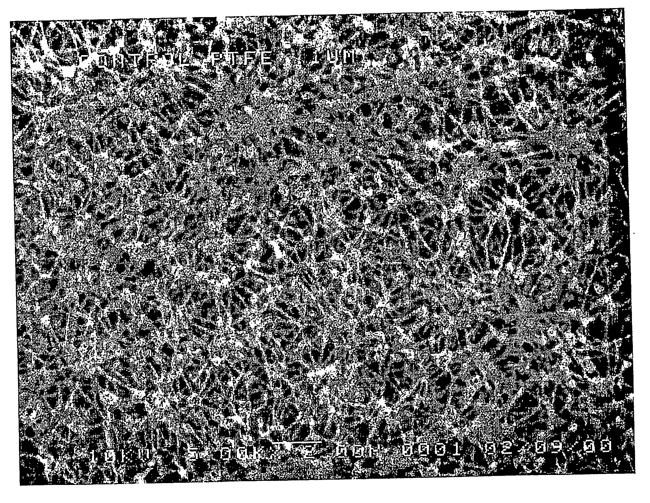
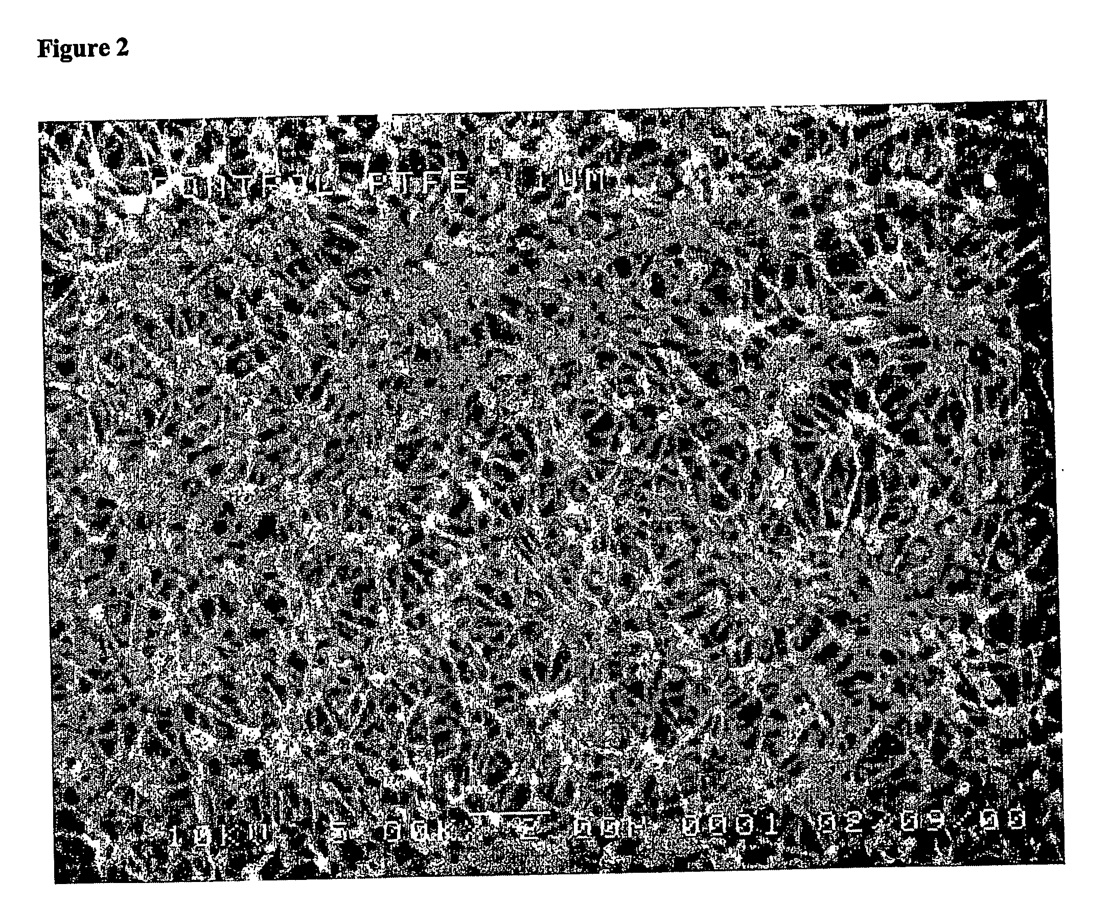
[0018] Asymmetric membranes have been fabricated using hot-filament chemical vapor deposition (HFCVD) to modify one side of a conventional poly(tetrafluoroethylene) (PTFE) membrane. The chemical structure of the modified layer is substantially (>98%) that of PTFE. These asymmetric membranes reduce the pressure drop required for operating separation processes. Thus, less energy must be expended for the filtration of chemicals and solvents and for gas / liquid separations. The asymmetric membranes of the present invention will be useful in the microelectronics industry.

Problems solved by technology

Significantly increasing one of these characteristics while signficantly reducing the other of these characteristics is undesirable.
Thus, liquids being filtered in this fashion experience a pressure drop across the membrane filter.
As the liquid passes from the upstream side of the membrane filter to the downstream side, dissolved gases come out of solution in the membrane resulting in outgassing of the liquid.
Membrane degradation leading to the chemical breakdown of the membrane composition usually results in extractable material which is released from the filter during use, thus compromising the purity, integrity and cleanliness of the fluid being filtered.
One disadvantage of fluorine-containing polymers is that they are hydrophobic and therefore membranes made from such polymers are difficult to wet with aqueous fluids or other fluids which have surface tensions greater than the surface energy of the membrane.
Another problem often encountered during the filtration of outgassing liquids with a hydrophobic membrane filter is that the membrane provides nucleating sites for dissolved gases to come out of solution under the driving force of the pressure differential, during the filtration process.
As these gas pockets grow in size due to continued outgassing, they begin to displace liquid from the pores of the membrane ultimately reducing the effective filtration area of the membrane.
During a filtration process the reduction of effective membrane area available for filtration due to dewetting of the membrane in a filter device results in a reduction of the overall filtration efficiency of the filter.
Thus, as the membrane filter dewets with time, the user is not able to purify or filter the same volume of process liquid per unit time as when the filter was newly installed and therefore completely wet.
This reduction of the overall throughput capability of the filtration process results in an increase in the user's time and cost to purify a unit volume of process liquid.
This premature filter changeout due to dewetting and not necessarily due to the exhaustion of the filter's dirt-holding capacity results in unscheduled downtime and increases the user's overall cost.
These adjustments also translate into higher operating costs for the user and increases the potential for malfunction of the other elements in the system as well as the potential for a process liquid spill due to the increased processing pressures.
The treatment is time consuming since it requires that the filter device be removed from the filtration system resulting in unscheduled downtime and can often result in the introduction of contaminants derived from the rewetting process into the process liquid passing through the filter.
While membrane manufacturers may have the expertise for handling and treating dewet filters, end users may not have the capabilities or the desire to perform such additional costly processing steps.
However, no coating process to modify the geometric nature of the pore structure of a PTFE membrane by the deposition of additional PTFE has been disclosed.
In electrolytic processes, such as disclosed by these patents, extractables derived from the coated diaphragms are not a substantial concern and the degree of porosity of the modified diaphragm is unimportant.
The modifying polymer composition can contain a surfactant and may contain excess modifying composition, both of which are sources of undesirable extractables.

Method used


Image

  • Preparation of asymmetric membranes using hot-filament chemical vapor deposition
  • Preparation of asymmetric membranes using hot-filament chemical vapor deposition
  • Preparation of asymmetric membranes using hot-filament chemical vapor deposition

Examples


Embodiment Construction

[0032] Bulk poly(tetrafluoroethylene), also known as PTFE, (CF2)n, and Teflon®, is characterized by superior mechanical and electrical properties that are important for a wide range of applications. For example, bulk PTFE is characterized by a low dielectric constant of about 2.1 and a low dielectric loss factor of less than about 0.0003 between about 60 Hz and 30,000 MHz. Bulk PTFE is also characterized by high chemical stability, exemplified by its immunity to even strong alkalis and boiling hydrofluoric acid; low water absorption, exemplified by its water uptake of only about 0.005 weight % in a 24 hour period; and high thermal stability, exemplified by its weight loss of only about 0.05 weight % per hour at about 400° C. A low coefficient of friction of between about 0.05 and about 0.08, and a low permeability constant also characterize bulk PTFE.

[0033] There have been proposed various film deposition processes devised with the aim of producing thin films having properties simi...


PUM

PropertyMeasurementUnit
temperatureaaaaaaaaaa
porosityaaaaaaaaaa

Abstract

One aspect of the present invention relates to a method for modifying one side of a PTFE membrane by using HFCVD to deposit a PTFE film on one side of the PTFE membrane. The precursor fluorocarbon gas is preferably hexafluoropropylene oxide, which upon pyrolysis under HFCVD conditions forms reactive CF2 species. The present invention also relates to a modified PTFE membrane having a PTFE film on only one side, wherein the PTFE film has a porosity of greater than about 30% and a dangling bond density of less than about 1018 spins / cm3. The invention further provides a method of filtering a liquid or gas or a mixture of the two, comprising passing the liquid or gas or mixture of the two through the modified PTFE membrane of the present invention.

Description

BACKGROUND OF THE INVENTION [0001] Porous membrane filters are utilized in a wide variety of environments to separate materials within a fluid stream. The membranes may be formed from a solid polymeric matrix, and have precisely controlled and measurable porosity, pore size and thickness. In use, the membrane filters generally are incorporated into a device, such as a cartridge, which, in turn, is adapted to be inserted within a fluid stream to remove particles, microorganisms or a solute from liquids and gases. Porous membranes are often employed as semi-permeable barriers between two or more miscible fluids. In these applications, the membranes control the transmission of components between the fluids, and in the absence of overriding intermolecular forces, e.g., based on charge, magnetism, and dipoles, they can generally be thought of as acting like sieves. As such, fluid components smaller than pores of the membrane can travel from one membrane surface to the other, but substanc...

Claims


Application Information

Patent Timeline
Patent Type & Authority Applications(United States)
IPC IPC(8): C23C16/00B01DB01D67/00B01D69/02B01D69/12B01D71/36C08J7/16C08J9/36C23C16/44
CPCB01D19/0031B01D2323/225B01D67/0088B01D69/02B01D69/127B01D71/36B05D1/60B05D2201/02B05D2506/15C08J7/047C08J7/16C08J2327/12C08J2327/18C08J2427/00B01D67/0002C08J7/0427
Inventor GLEASON, KARENKSALIMARO, RICHARDF
Owner MASSACHUSETTS INST OF TECH
Why Eureka
Try Eureka