
Well cementing material

a well cementing and slurry technology, applied in the direction of ceramicware, solid waste management, sustainable waste treatment, etc., can solve the problems of difficult to combine with conventional cementing materials, mechanical strength degradation, and large increase in the permeability of hardened materials

Inactive Publication Date: 2006-04-13
INST FR DU PETROLE
View PDF4 Cites 32 Cited by
  • Summary
  • Abstract
  • Description
  • Claims
  • Application Information

AI Technical Summary

Benefits of technology

[0026] The cementing material according to the invention can further comprise an accelerating agent for controlling the setting time of the slurry.
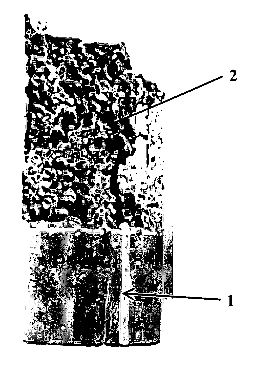
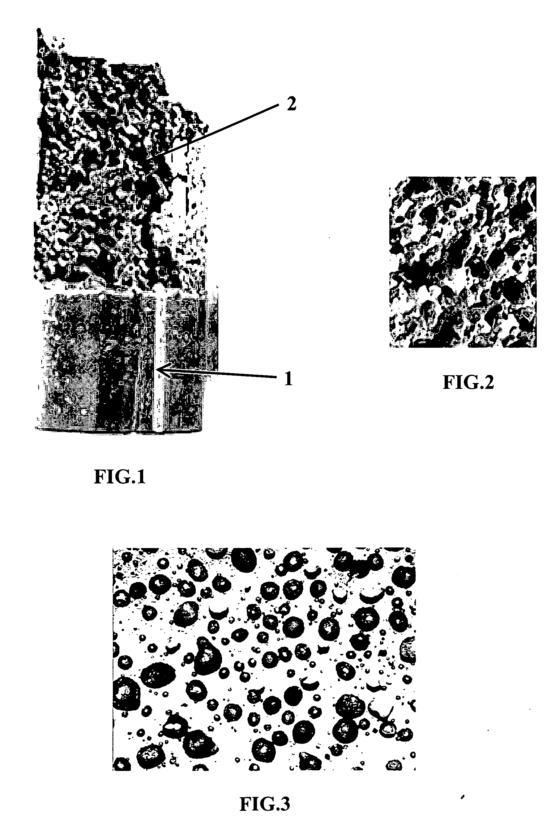
[0034] In the present invention, the cement material of the walls separating the foam bubbles thus has a higher compactness than the materials commonly used in the profession. The porosity of the cement pastes of these new materials was measured by means of a mercury-pump porosimeter and it is below 12%, whereas the porosity of the cement pastes of conventional foamed cements is above 25%.
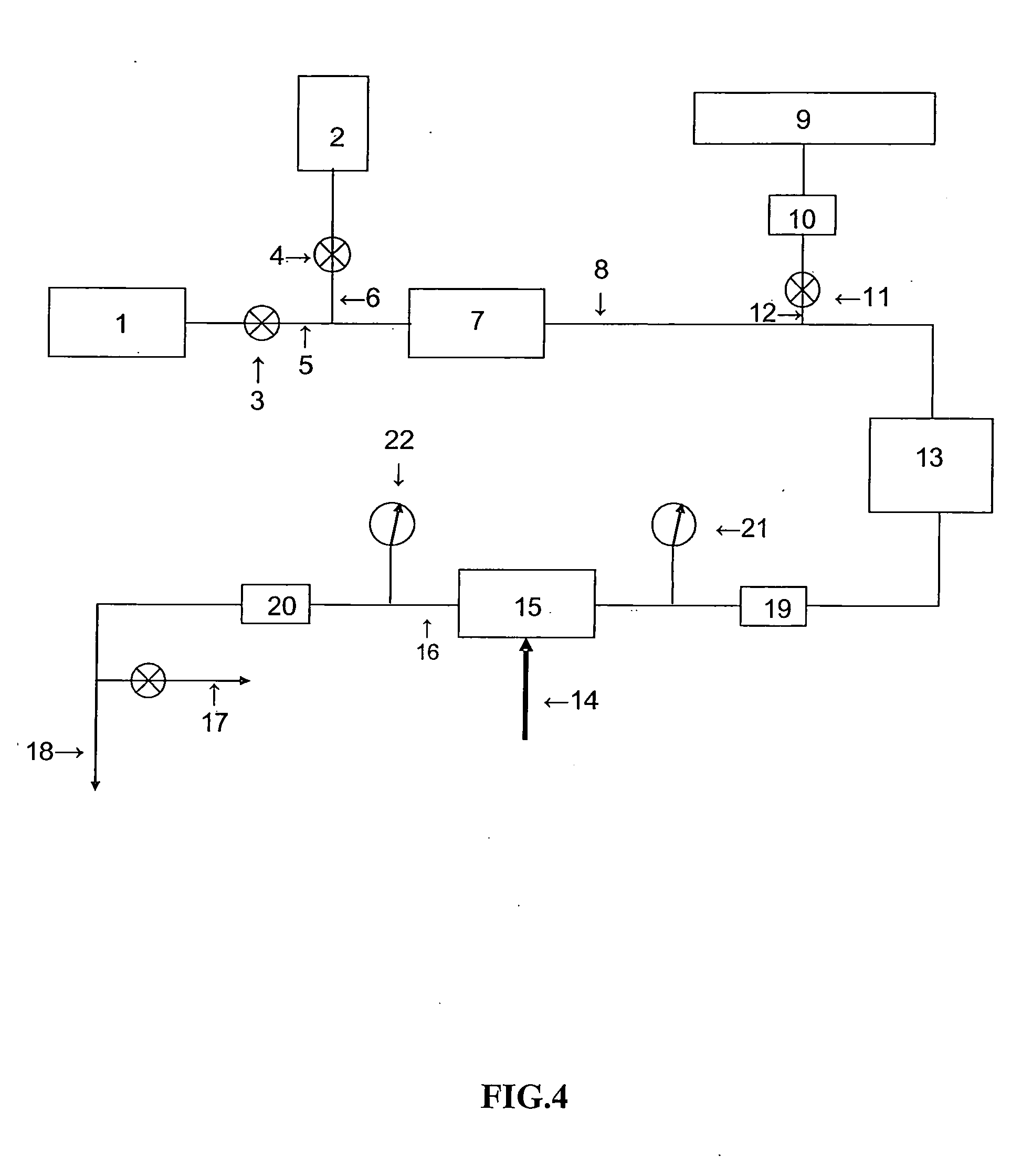
[0036] High-performance cements being very fluid, it is difficult to obtain, from these slurries, a stable foam, i.e. whose bubbles do not coalesce. If the bubbles coalesce before the cement hardens, the hardened material will be very permeable and have little mechanical strength. Adjustment of the proportions of the various aggregates that make up the cement slurry according to the invention allows to obtain a stable cement foam, despite the high fluidity of the cementing material. The invention described in this patent allows to obtain stable high-performance cement foams and therefore, in fine, a hardened material of very low permeability and thus of improved durability.
[0038] Thus, the foamed cement formulations according to the present invention allow to carry out all the cementing operations required in the case of wells drilled in low-cohesion formations. The formulations of the present invention can also be used for cementing cavernous, fault zones and more generally zones where fluid losses occur during drilling.

Problems solved by technology

These two conditions are difficult to combine with conventional cementing materials.
According to the above formula, these two means lead to a mechanical strength degradation and, simultaneously, to a great increase in the permeability of the hardened material.
When the formations drilled are fragile and unconsolidated, it is impossible to carry out operations with a dense cement slurry for fear of exceeding the fracture pressure of the formations.
This problem is notably encountered when cementing the casings of offshore wells or wells drilled in mature fields.
One drawback is the destruction of the balls under the effect of the hydrostatic pressure.
Another drawback of hollow glass balls comes from the destruction, in the hardened cement, of the walls of the balls as a result of pozzolanic reactions.
This destruction translates into an increase in the permeability of the cement matrix.
This high water amount, necessary to lower the cement slurry densities and to optimize the rheology, generates a high porosity which translates into poor properties of the cement sheath in terms of permeability, mechanical strength, cracking and durability.
It is well-known that the viscosity of suspensions increases exponentially with the volume fraction in solid particles: the significant increase in the cement slurry viscosity is very serious from an operational point of view because, in this case, the material can no longer be set in place by pumping.
However, the densities of these high-performance cements as described in document EP-950,034 are above 1.9 g·cm−3 and they are therefore not suitable for cementing fragile and unconsolidated zones such as those encountered in deep-sea drilling or for cementing wells in depleted reservoirs.
These materials thus have the same drawbacks as conventional cements containing hollow microspheres: microsphere crushing during pumping in the well, pozzolanic reaction between the portlandite and the silica contained in the microsphere walls.
Furthermore, it is impossible to vary the density of the cement during cementing.

Method used


Image

  • Well cementing material
  • Well cementing material
  • Well cementing material

Examples


Embodiment Construction

[0043] According to the invention, the low density and the excellent physical properties (compressive strength and permeability) of the cementing material formulations are optimized by combining the following constituents: [0044] a hydraulic binder from the group consisting of the Portland cements and other hydraulic binders, for example of aluminous cement type, whose alumina content is above 30%, or sulfoaluminous cement, or plaster, [0045] a microsilica (also referred to as silica fume) of grain size ranging between 0.1 μm and 30 μm (the BET surface area can range between 10 and 30 m2 / g, preferably 18 m2 / g), whose proportion in the composition according to the invention ranges between 15% and 50% by mass in relation to the mass of hydraulic binder. In the invention, the microsilica can be replaced by fly ash (silico-aluminous, sulfocalcic or silico-calcic particles), [0046] a mineral addition of grain size ranging between 1 μm and 500 μm (which corresponds to a D50 ranging betwee...


PUM

PropertyMeasurementUnit
grain sizeaaaaaaaaaa

Abstract

The present invention relates to a formulation of a high-performance foamed cement material, comprising: at least one hydraulic binder, microparticles whose grain size ranges between 0.1 and 30 μm, whose proportion ranges between 15% and 50% by mass in relation to the mass of hydraulic binder, mineral particles whose grain size ranges between 1 and 500 μm, whose proportion ranges between 10% and 35% by mass in relation to the mass of hydraulic binder, the proportion of particles being lower than the proportion of microparticles, a hydrosoluble polymer thinning agent whose proportion ranges between 0.1% and 8% by mass in relation to the mass of hydraulic binder, water whose proportion is at most 40% by mass in relation to the mass of hydraulic binder, a foaming agent whose proportion ranges between 0.1% and 10% by mass in relation to the mass of hydraulic binder.

Description

FIELD OF THE INVENTION [0001] The present invention relates to a slurry for cementing a well, notably a well intended for exploration or development of underground reservoirs, such as hydrocarbon or geothermal reservoirs. The invention provides new cementing material formulations having simultaneously low densities, high mechanical properties and a low permeability. BACKGROUND OF THE INVENTION [0002] Hydrocarbon development well cementing is a complex operation with multiple goals: mechanically secure the casing strings in the geologic formation, isolate a producing layer from adjacent layers, protect the strings against the corrosion due to the fluids contained in the layers crossed through. The cement sheaths therefore have to provide good mechanical strengths and low permeability to the fluids and to the gas contained in the formations drilled. [0003] Under certain geothermal or hydrocarbon reservoir development conditions, it is essential to have cementing materials with both lo...

Claims


Application Information

Patent Timeline
Patent Type & Authority Applications(United States)
IPC IPC(8): C04B16/08C04B20/00
CPCC04B28/02C04B14/04C04B18/146C04B20/008C04B24/26C04B38/10C04B2103/40C04B2103/0053C04B28/06C04B28/065C04B2103/0035C04B2103/0036C09K8/473Y10S106/01Y02W30/91
Inventor LECOLIER, ERICRIVEREAU, ALAIN
Owner INST FR DU PETROLE
Learn More