Hard-carbon coated sliding member

Inactive Publication Date: 2006-05-04
NISSAN MOTOR CO LTD +1
View PDF3 Cites 10 Cited by
  • Summary
  • Abstract
  • Description
  • Claims
  • Application Information

AI Technical Summary

Benefits of technology

[0010] Regardless of the difference in measurement methods, it is desired that the friction coefficients of the hard carbon coatings of JP2003-247060A and JP2004-099963A be further lowered. In addition, the process of forming the hard carbon coating of JP2004-099963A is complicated since the size and number of the silver clusters on the hard carbon coating needs to be controlled during coating formation. The process of forming the hard carbon coating of JP2004-115826A is also complicated since both of the metal content and the oxygen content of the hard carbon coating need to be controlled during coating formation. The simplification of these hard carbon coating formation processes is thus desired. Further, the hard carbon coating of JP2004-1

Problems solved by technology

In addition, the process of forming the hard carbon coating of JP2004-099963A is complicated since the size and number of the silver clusters on the hard carbon coating needs to be controlled during coating formation.
The process of forming the hard carbon coating of JP2004-115826A is also complicated since both of the metal content and the oxygen content of the hard carbon coating need to be controlled during coating formation.
Although the friction

Method used


Image

  • Hard-carbon coated sliding member
  • Hard-carbon coated sliding member

Examples


example 1

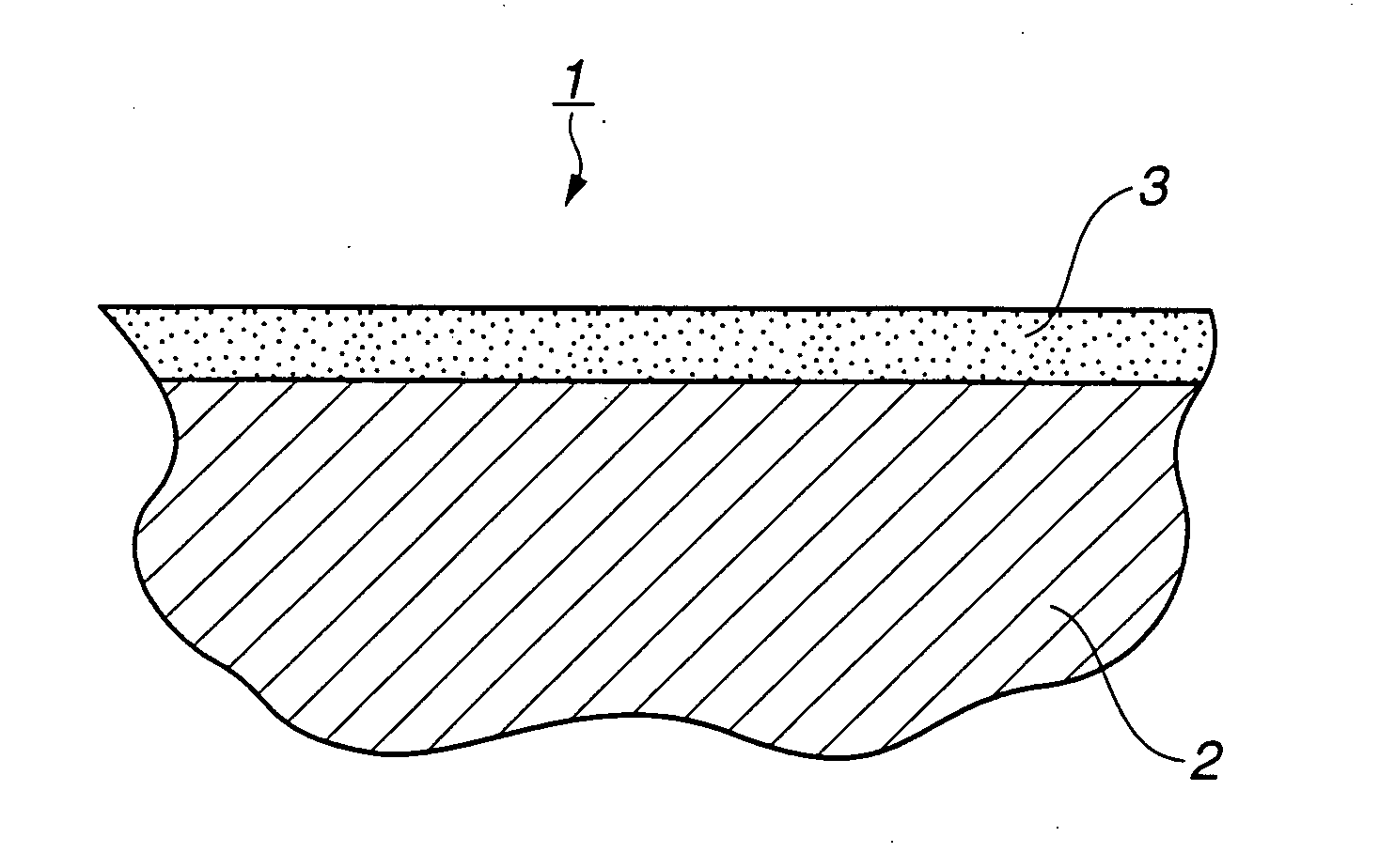
[0031] A disk plate of carburized steel SCM4 15 (according to JIS G 4105) having a diameter of 30 mm and a thickness of 3 mm was prepared as a base substrate. A surface of the disk plate was superfinished to an arithmetic mean roughness Ra of 0.020 μm (according to JIS B 0601). A hard carbon coating was formed on the superfinished surface of the disk plate by magnetron sputtering in an atmosphere of argon gas. In the magnetron sputtering, a graphite disk plate was uses as a target. In order to dope a certain amount of cobalt in the hard carbon coating, a sector cobalt plate was attached onto the graphite disk target. The graphite disk target had a radius of 80 mm, whereas the sector cobalt plate had a radius of 80 mm and a vertex angle of 7.5° to cover 1 / 48 of the graphite target. In advance of the formation of the hard carbon coating on the steel disk plate, a coating growth rate was determined by performing magnetron sputtering under the same conditions as above except that only a...

example 2

[0043] A hard-carbon coated disk plate was prepared in the same way as in Example 1, except that a hard carbon coating of the disk plate was formed by magnetron sputtering with a sector nickel plate being attached onto a graphite disk target to dope a certain amount of nickel into the hard carbon coating. The graphite disk target had a radius of 80 mm, whereas the sector nickel plate had a radius of 80 mm and a vertex angle of 7.5° to cover 1 / 48 of the graphite target. The sputtering time was controlled in such a manner as to adjust the thickness of the hard carbon coating to 1.0±0.3 μm.

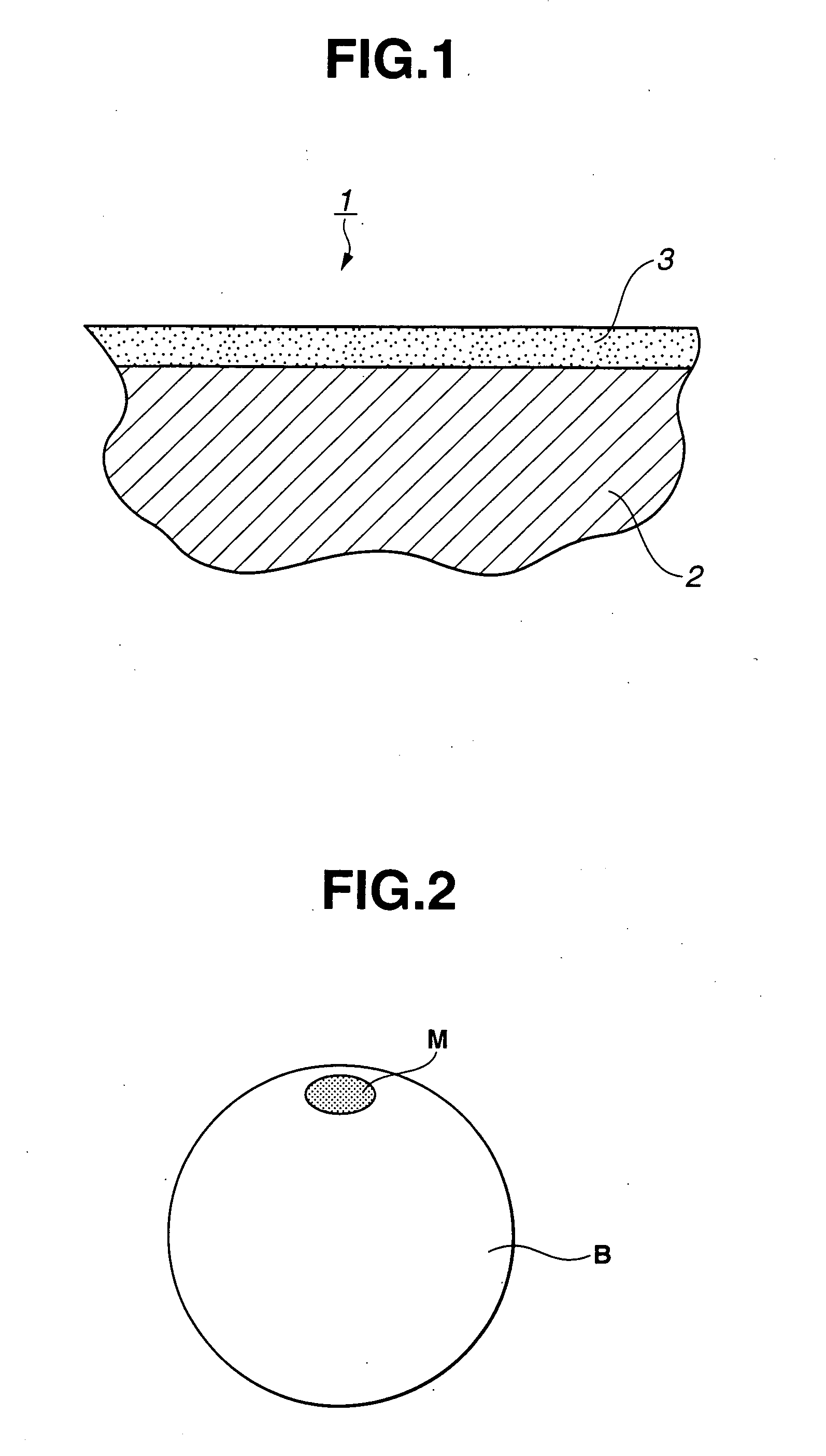
[0044] The surface roughness, composition and sliding characteristics of the thus-obtained hard carbon coating were tested in the same way as in Example 1. The hard carbon coating had a surface roughness Ra of 0.020 μm, a nickel content of 25 atomic % (as measured by XPS), a hydrogen content of 0.1 atomic % or less and a friction coefficient of 0.023, and the opposing member had a sliding mark of 52...

example 3

[0046] A hard-carbon coated disk plate was prepared in the same way as in Example 1, except that a hard carbon coating of the disk plate was formed by magnetron sputtering with both of a sector cobalt plate and a sector nickel plate being attached onto a graphite disk target to dope cobalt and nickel into the hard carbon coating of the disk plate. The graphite disk target had a radius of 80 mm, whereas each of the sector cobalt plate and the sector nickel plate had a radius of 80 mm and a vertex angle of 3.75° to cover 1 / 96 of the graphite target. The sputtering time was controlled in such a manner as to adjust the thickness of the hard carbon coating to 1.0±0.3 μm.

[0047] The surface roughness, composition and sliding characteristics of the thus-obtained hard carbon coating were tested in the same way as in Example 1. The hard carbon coating had a surface roughness Ra of 0.015 μm, a cobalt content of 14 atomic %, a nickel content of 11 atomic %, a hydrogen content of 0.1 atomic % o...


PUM

PropertyMeasurementUnit
Percent by atomaaaaaaaaaa

Abstract

There is provided a sliding member including a base substrate and a hard carbon coating formed on the base substrate to define at least a surface for sliding contact with an opposing member. The hard carbon coating contains therein at least one of cobalt and nickel in an amount of 1.4 to 39 atomic %.

Description

BACKGROUND OF THE INVENTION [0001] The present invention relates to a sliding member having a hard carbon coating to show excellent low-friction sliding characteristics, particularly of the kind suitable for use with a lubricating oil such as an automotive engine oil or transmission oil. [0002] A hard carbon coating is formed of amorphous carbon-based material such as amorphous carbon or hydrogen-containing amorphous carbon (a-C:H), i-carbon (i-C), diamond-like carbon (DLC) or the like. For the formation of this hard carbon coating, a vapor phase reaction process is often used including plasma chemical vapor deposition (CVD) in which the hard carbon coating is deposited by the plasma decomposition of hydrocarbon gas and ion beam vapor deposition process which the hard carbon coating is deposited by a beam of carbon or hydrocarbon ions. [0003] It is well known that the hard carbon coating has not only a high hardness, surface smoothness, high wear resistance but also a low friction c...

Claims


Application Information

Patent Timeline
IPC IPC(8): B32B9/00B32B15/04
CPCC23C14/0605Y10T428/30F16C33/16C23C30/00Y10T428/31678
Inventor OKAMOTO, YUSUKEYASUDA, YOSHITERUMIYAKE, SHOJIRO
Owner NISSAN MOTOR CO LTD
Why Eureka
Try Eureka